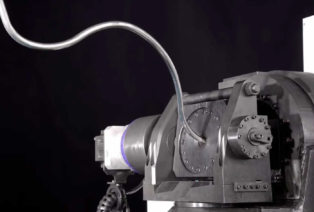
Bent tube structures, known for their light weight, high strength, and ease of processing, are widely used in industries such as automotive, home appliances, aerospace, and military, including applications like automotive exhaust pipes and aerospace engine pipelines.
Freeform bending technology is a significant innovation in the field of plastic forming. It allows for precise, continuous, die-free bending of tubes, profiles, and wires, making it particularly suitable for complex spatial shapes and components with continuously changing bending radii.
In the actual production and assembly of bent tubes, the key bottleneck has always been how to quickly, efficiently, and accurately measure the dimensions of the tubes and verify if they meet design requirements.

3D Optical Bent Tube Measurement System
The 3D optical bent tube measurement system uses multiple high-frame-rate, high-resolution industrial cameras to capture 2D images of bent tubes from various angles. By leveraging technologies such as image recognition, stereo vision, photogrammetry, multi-camera spatial calibration, and 3D reconstruction, this system can quickly achieve intelligent, efficient, and online measurement and inspection of the 3D shapes of bent tubes.
Automated Online Inspection of Bent Tubes
In the freeform bending process, feedback on the bending parameters of the CNC tube bender is a critical step. By establishing a process of 3D bent tube measurement and comparative analysis, it is possible to achieve efficient, online, automated inspection and digital processing of complex bending components.
During the production process of CNC tube benders, the geometric information of the tube model needs to be converted into freeform bending process information to obtain processing instructions that can be directly input into the freeform bending equipment.
Using a 3D optical bent tube measurement system, the processed tube can be measured to accurately determine bending parameter deviations in XYZ and LRA (PBC). By comparing theoretical values with measured values, the system can provide output for bend correction and can directly connect with the tube bender to compensate and guide the analysis of part processing. For bends that do not meet the requirements, the system can modify the bending machine’s forming process parameters in real time.
See also How to reduce the deformation of the plate rolling process?
Reverse Engineering and Assembly Relation 3D Inspection of Bent Tubes
The 3D optical bent tube measurement system can be used for the reverse engineering of bent tube parts, measuring existing physical bent tube parts to obtain their 3D data. Additionally, it can be used to find reasonable spaces for safely and reliably arranging bent tube parts within existing assembly structures.
While measuring the tubes, the position and dimensions of connecting parts such as welded flanges and brackets are also important. The 3D optical bent tube measurement system can measure the 3D data at these tube interfaces, accurately obtaining the positional information of these key structures to ensure the accuracy and reliability of tube assembly.
See also Three-axis and Six-axis 3D Freeform Bending Systems
Application Scenarios of 3D Optical Bent Tube Measurement System
- Automatic Machine Adjustment: Calibration and adjustment of the tube bender, iterative determination of process parameters for new bent tube parts. This method improves efficiency more than tenfold compared to traditional means.
- Digital Inspection: Inspection of tubes and pipe fittings in aerospace, automotive engine oil and gas lines, air conditioning and refrigeration, thermal management piping, and new energy vehicles.
- Tube Shape Registration and Reverse Engineering: Registration or reverse engineering of tube shapes during new product design, production of products without drawings, or in special handmade bending in R&D processes.
- Digital Gauges – Sheath Deviation: For tube measurement, sheath deviation expresses the measurement accuracy of a tube. As shown in the figure, for bending sections, the radial deviation at the entry and exit points of the bend is the sheath deviation of the bending point. For the tube ends, it is the axial and radial deviations at the start or end point, representing the sheath deviation.