Metal Bending
Bending sheet metal is a common and vital process in the manufacturing industry, it is an operation that involves using forces to change the shape of a sheet. Sheet metal bending is the plastic deformation of the work over an axis, creating a change in the part's geometry. Similar to other metal forming processes, bending changes the shape of the workpiece, while the volume of material will remain the same.
Sheet metal is referenced with regard to the workpiece when bending processes are discussed in this art. However, many of the processes covered can also be applied to plate metal as well. References to sheet metal workpieces may often include sheet metal plates. Some bending operations are specifically designed for the bending of differently shaped metal pieces. Tube and rod bending is also widely performed in modern manufacturing.
Bending can be defined simply as a forming operation in which the metal is deformed along a straight axis. Both compression and tension occur when bending sheet metal. The inside radius of the bent metal is in compression, or being squeezed together. The outside bend radius is in tension, or being stretched.
Bending processes differ in the methods they use to plastically deform the sheet or plate. Work piece material, size, and thickness are important factors when deciding on a type of metal bending process. Also important is the size of the bend, bend radius, angle of bend, the curvature of bend, and location of bend in the workpiece. Sheet metal process design should select the most effective type of bending process based on the nature of the desired bend and the work material. Many bends can be effectively formed by a variety of different processes and available machinery will often determine the bending method.
What is the machinery used for metal bending?
Bending is done using Press Brakes. Press Brakes normally have a capacity of 20 to 200 tons to accommodate stock from 1m to 4.5m (3 feet to 15 feet). Larger and smaller presses are used for specialized applications. Programmable back gages and multiple die sets available currently can make for a very economical process.
Applications
Sheet metal bending is one of the essential procedures in the metal processing industry. For example, it is an important phase in the automotive companies since they work with different shapes to get the perfect automobile part that works with their design. The process can be at an industrial level, where it is ideal for creating big engine parts. Nevertheless, it can also be used in making little parts for the replacement of worn-out engine parts. While there are many processes involved in the operation, all sheet metal bending methods consider standard techniques to ensure precision across its production.
Material Properties
The effect that material properties will have in response to the conditions of manufacture will be a factor in sheet metal process design. Usually, sheet metal bending is performed cold bending but sometimes the work may be heated, to either warm or hot working temperature.
Metal bending enacts both tension and compression within the material. Mechanical principles of metals, particularly with regard to elastic and plastic deformation, are important to understanding sheet metal bending and are discussed in the fundamentals of metal forming section.
The material is stressed beyond the yield strength but below the ultimate tensile strength. The surface area of the material does not change much. In some cases, bending may produce a small change in sheet thickness. For most operations, however, bending will produce essentially no change in the thickness of the sheet metal. In addition to creating a desired geometric form, bending is also used to impart strength and stiffness to sheet metal, change a part’s moment of inertia, for the cosmetic appearance, and to eliminate sharp edges. Bending usually refers to the deformation of one axis.
This is done to achieve the desired form or shape needed for a manufacturing process. The external force used alters only the external features of the sheet. However, parameters of the one type of sheet metal such as length and thickness remain the same. The malleability of the sheet metal further allows it to undergo various shaping processes.
Standard die of the bending process
Bending is a flexible process by which many different shapes can be produced. Standard die sets are used to produce a wide variety of shapes. The material is placed on the die and positioned in place with stops and/or gages.
Most sheet metal bending operations involve a punch die type setup, although not always. There are much different punch die geometries, setups, and fixtures. Tooling can be specific to a bending process and a desired angle of bend. Bending die materials are typically gray iron or carbon steel, but depending on the workpiece, the range of punch-die materials varies from hardwood to carbides. Force for the punch and die action will usually be provided by a press. A workpiece may undergo several metal bending processes. Sometimes it will take a series of different punch and die operations to create a single bend. Or many progressive bending operations to form a certain geometry.
Metal Bending Processes
V bending
One of the most common types of sheet metal manufacturing processes is V bending. The V-shaped punch forces the work into the V-shaped die and hence bends it. This type of process can bend both very acute and very obtuse angles, also anything in between, including 90 degrees.
Advantage
A very good method for obtaining a given bend angle, V bending is undoubtedly the most common method used with press brake bending. An acute angle ground on both the punch and die can provide adequate overbending of the metal. Also, the bending amount can be altered by adjusting the amount of coining the metal undergoes at the bottom of the press stroke.
Disadvantage
One disadvantage to V bending is that it often requires the part to be rotated in such a manner that sometimes is difficult to incorporate in a progressive die. An advantage is that it often requires less force to create the bend compared with conventional wipe bending.
Air Bending
Air bending is a simple method of creating a bend without the need for lower die geometry, it is done with the punch touching the workpiece and the workpiece, not bottoming in the lower cavity. This is called air bending.
The sheet metal is supported by two surfaces a certain distance apart. A punch exerts a force at the correct spot, bending the sheet metal between the two surfaces. As the punch is released, the workpiece ends up with less bend than that on the punch (greater included angle). This is called spring-back. The amount of spring back depends on the material, thickness, grain, and temper. The spring back usually ranges from 5 to 10 degrees. Usually, the same angle is used in both the punch and the die to minimize setup time. The inner radius of the bend is the same as the radius on the punch.
Channel bending
Punch and die are manufactured with certain geometries, in order to perform specific bends. Channel bending uses a shaped punch and dries to form a sheet metal channel. A U bend is made with a U-shaped punch of the correct curvature.
Many bending operations have been developed to produce offsets and form sheet metal for a variety of different functions.
Some sheet metal bending operations involve the use of more than 2 dies. Round tubes, for example, can be bent from sheet metal using a multiple-action machine. The hollow tube can be seamed or welded for joining.
Bottoming and Coining Bending
Bottoming or Coining is the bending process where the punch and the workpiece bottom on the die. This makes for a controlled angle with very little spring back. The tonnage required on this type of press is more than in air bending. The inner radius of the workpiece should be a minimum of 1 material thickness in the case of bottoming; and up to 0.75 material thickness, in the case of coining.
Wipe Bending (Edge Bending Process)
One of the most common methods used, but not always the most effective, is simple wipe bending.
In the wipe bending method, the sheet metal is held against a wipe die by a pressure pad. The punch then forces against the edge of the sheet that extends beyond the die and pressure pad, causing it to bend over the end of the die.
Unfortunately, this method does not allow for much overbending other than the very slight acute angle that can be achieved by wiping the side extremely tight.
Even though wipe bending effectively creates a bend, controlling the bend angle is very difficult. This method is not well-suited to bending high-strength metals or for parts requiring precision bend angle tolerances. Wipe bending can be improved by capturing the outside profile of the radius with the forming die section.
However, it might not be ideal for creating obtuse bend angles as you’d require a more complex piece of equipment capable of delivering horizontal force.
Rotary bending
The rotary bending process provides benefits over a standard edge bending operation, in that it eliminates the need for a pressure pad and it is capable of bending over 90 degrees without any horizontally acting equipment. Rotary bending is relatively new and is gaining popularity in the manufacturing industry.
Rotary bending forms the work by a similar mechanism as edge bending. However, rotary bending uses a different design than the wiping die. A cylinder, with the desired angle cut out, serves as the punch. The cylinder can rotate about one axis and is securely constrained in all other degrees of motion by its attachment to the saddle. The sheet metal is placed cantilevered over the edge of the lower die, similar to the setup in edge bending. Unlike in edge bending, with rotary bending, there is no pressure pad. Force is transmitted to the punch causing it to close with the work. The groove on the cylinder is dimensioned to create the correctly angled bend. The groove can be less than or greater than 90 degrees allowing for a range of acute and obtuse bends. The cylinder V groove has two surfaces. One surface contacts the work transmitting pressure and holding the sheet metal in place on the lower die. As force is transmitted through the cylinder it rotates, causing the other surface to bend the work over the edge of the die, while the first surface continues to hold the work in place. Rotary bending provides a good mechanical advantage.
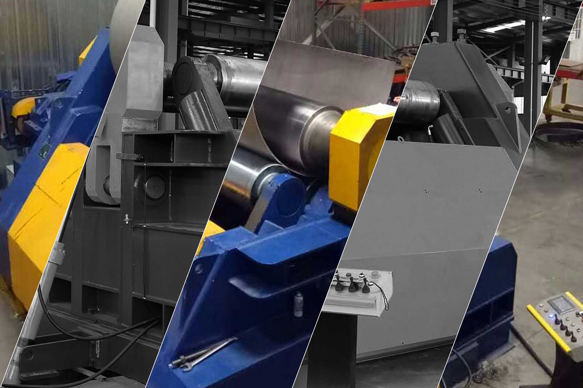
Roll Bending
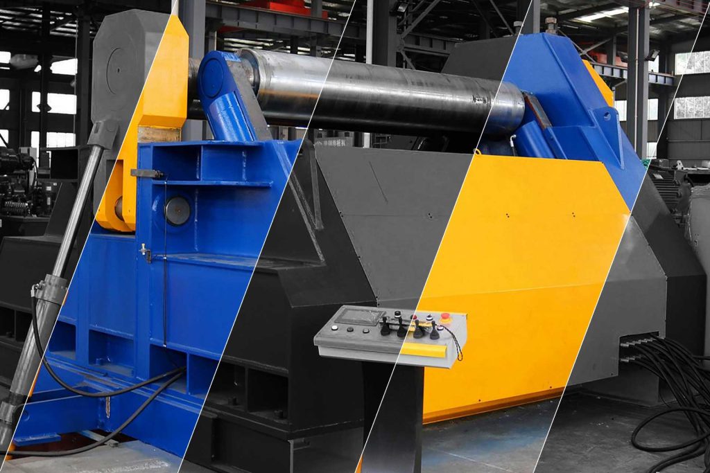
Roll bending provides a technique that is useful for relatively thick work.
Although sheets of various sizes and thicknesses may be used, this is a major manufacturing process for the metal bending of large pieces of plate. Roll bending uses three rolls to feed and bend the plate to the desired curvature. The arrangement of the rolls determines the exact bend of the work. Different curves are obtained by controlling the distance and angle between the rolls. A moveable roll provides the ability to control the curve. The work may already have some curve to it, often it will be straight. Beams, bars and other stock metal is also bent using this process. Two Roll Bending vs. Three Roll Process Note that the drawbacks of the three roll systems, whether pinch or pyramid type, are that the workpiece
is not confined during the roll bending process, i.e., bending takes place “in the air.” When rolling parts this way to some desired shape and tolerance, several passes might be required with roll adjustments necessary after each pass. This is relatively slow and requires considerable skill on the operators’ part.
The Two-Roll Bending Principal
The Two Roll Principle method is comprised of a steel top roll and a urethane bottom roll. A segment of this top roll is pushed into the urethane bottom roll, and this deflecting volume of urethane functions the same as a hydraulic fluid in a hydroforming process, exerting very high pressures against the steel roll. When sheet metal is inserted between two such rolls, the urethane wraps the sheet metal tightly against the steel roll (similar to a radius forming urethane press brake die), and since the urethane roller is driven, the sheet metal is roll-formed into a precise radius. Allowing for the natural spring back of the material, this radius remains uniform irrespective of whether the shape of the part being formed is a complete circle, or is only a segment of a circle. In most applications, this will eliminate the necessity of either performing or cutting off the ends. The flat spots on the leading and trailing edges are very minimal (approx. one to four material thicknesses, depending on the type of material). Otherwise difficult-to-roll sheet metal parts, such as those with perforations, cut-outs, uneven feeding or trailing edges, embossed parts, etc. can be formed without kinking or fluting. Finally, the relatively soft urethane surface will not mar or scratch finished surfaces.
Getting Parts With Different Radii
In all cases, the radius of the rolled part is controlled by the radius of the top roll and the natural spring-back of the material (so accurate is the pressure of the two-roll system that if in a given run, parts with the wrong radius start coming off the 2-roll bending machine, the thing to do is to check the material quality, not the machine setting). In other words, the metal rolling machine has a “zero tolerance”, meaning that variations in the free diameter of the rolled part are due only to the variations (hardness, temper, and thickness of material) in the natural spring-back of the material.
Some of the disadvantages of a Three Roll, Pinch-Type or Pyramid-Type system include:
- The ends of blanks must be pre-formed on other equipment (or cut off which means material waste).Flat areas may form between cutouts and perforations in a part, eliminating the possibility of making such openings while the piece part is flat, requiring a more complex process.Fluting or kinking of material will occur especially in parts with cutouts and perforations.It is practically impossible to roll prefinished (polished, painted, enameled, etc.) material without the possibility of damaging finished surfaces (cracking and scratching).
Roll Forming
Roll forming is like sheet metal fabrication where thin flat sheets of metal are bent into a 3D shape, but in contrast, these bends are formed gradually and continuously so a constant 2D cross-sectional shape comes out the other end like an extrusion. Long strips or coils of flat metal are fed into one end of a roll forming line where it passes through a series of rolling dies and comes out the end in a totally new shape.
Roll forming of sheet metal is a continuous manufacturing process, that uses rolls to bend a sheet metal cross-section of a certain geometry. Often several rolls may be employed, in series, to continuously bend stock. Similar to shape rolling, roll forming does not involve material redistribution of the work, only bending. Like shape rolling, roll forming usually involves bending the work in sequential steps. Each roll will form the sheet metal to a certain degree, in preparation for the next roll. The final roll completes the geometry.
Channels of different types, gutters, siding, and panels for structural purposes are common items manufactured in mass production by roll forming. Rolls are usually fed from a sheet metal coil. The entry roll is supplied as the coil unwinds during the process. Once formed, continuous products can be cut to desired lengths to create discrete parts. Closed sections such as squares and rectangles can be continuously bent from a sheet metal coil. Frames for doors and windows are manufactured by this method. Sheet metal coil is often rolled bent into a thin-walled pipe that is welded together, at its seam. The welding of the continuous product is incorporated into the rolling process. Roll forming of channels is a continuous alternative to a discrete channel bending process.
This channel could be produced with a punch and die. However, in that case, the length of the channel would be limited by the length of the punch and die. Roll forming allows for a continuous part, (limited practically to the length of the sheet metal coil), that can be cut to whatever size needed. Productivity is also increased, with the elimination of loading and unloading of work. Rolls for sheet metal roll forming are typically made of grey cast iron or carbon steel. Lubrication is important and affects forces and surface finish. Sometimes rolls will be chromium-plated to improve surface quality.
For the most part, other processes can be used to make the same parts that are achieved by roll forming. If very long lengths or high volumes are needed though, roll forming offers distinct economic advantages and comes with great dimensional reliability as well.
Corrugating Bending
Corrugating is a type of roll-forming bending process in which a symmetrical bend is produced across the width of sheet metal and at a regular interval along its entire length. A variety of shapes are used for corrugating, but they all have the same purpose, to increase the rigidity of the sheet metal and increase its resistance to bending moments. This is accomplished by a work hardening of the metal and a change in the sheet’s moment of inertia, caused by the bend’s geometry. Corrugated sheet metal is very useful in structural applications and is widely used in the construction industry.
Design Considerations
The bend radius should be kept the same for all radii in the part to minimize set up changes. Bend radius guidelines are as follows:
For most materials, the minimum inner radius should be at least 1 material thickness.
As a general rule, bending perpendicular to the rolling direction is easier than bending parallel to the rolling direction. Bending parallel to the rolling direction can often lead to fracture in hard materials, thus bending parallel to the rolling direction is not recommended for cold-rolled steel > Rb 70, and no bending is acceptable for cold-rolled steel > Rb 85. Hot rolled steel can be bent parallel to the rolling direction.
The minimum flange width should be at least 4 times the stock thickness plus the bending radius. Violating this rule could cause distortions in the part or damage to the tooling or operator due to slippage.
Slots or holes too close to the bend can cause distortion of these holes. Holes or slots should be located a minimum of 3 times the stock thickness plus the bend radius. If it is necessary to have holes closer, then the hole or slot should de be extended beyond the bend line.
Dimensioning of the part should take into account the stack-up of dimensions that can happen and mounting holes that can be made oblong should be.
Parts should be inspected in a restrained position so that the natural flexure of the parts does not affect measurements. Similarly, inside dimensions in an inside bend should be measured close to the bend.