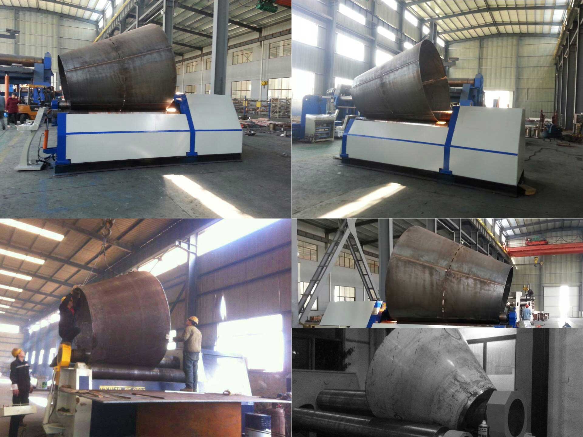
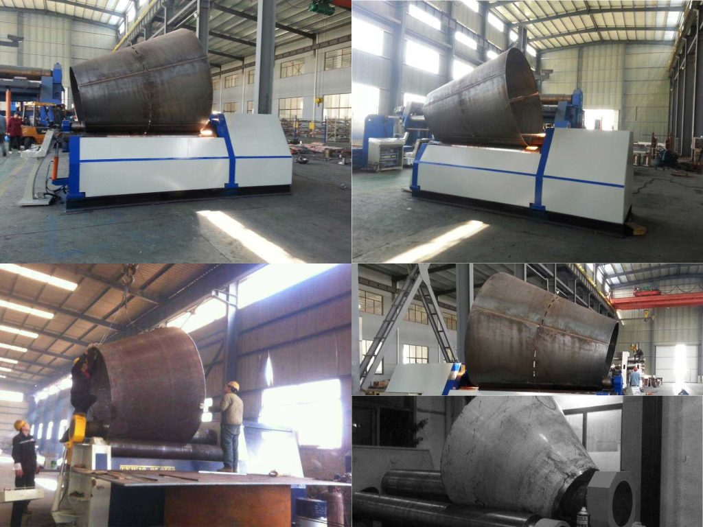
Principle of Roll Cone
The cylinder and the cone can be regarded as the cylinder and the cone of the workpiece are rotated 360 degrees around the rotation centerline in the same plane. The bar of the cylindrical workpiece is parallel to the rotation center line, and the busbar and the rotation center of the cone workpiece. Tilt line. Rolling cylinders and cones on a roll bending machine are based on the principle of three-point bending. The coiling process mainly includes the following three steps. First, the workpiece is fed into the work roll of a roll bending machine, and a roll is on the workpiece. Above the top is called the top roll, two below the workpiece, called the bottom roll, which is a three roll coiler; the four roll baler has three rolls below the workpiece and one inside the same vertical plane of the top roll, called the middle-lower roller, the other two on both sides of the upper roller, called the side roller, the upper roller can bend the workpiece with any two rollers of the side roller and the middle-lower roller. This article only discusses two rollers or side The symmetrical arrangement of the roller and the upper roller; the second step is the work roller for the feed movement, that is, the three-point bending, some of the plate rolling machine is the upper roller for feeding down, some of the lower roller or side roller for upward For movement, for narrative convenience, according to the principle of relative motion, the workpiece and the lower roller or side roller as stationary, the upper roller for the depressing movement; the volume of the cylindrical workpiece on the roller is parallel with the lower roller, roll When the roller is pressed down by the roller on the workpiece, it is inclined with the lower roller; the more the pressing amount is, the busbar and the nearby cable that the workpiece is in contact with the upper roller The larger; The third step is the work rolls by rotational movement so that rotation of the workpiece while maintaining constant the amount of reduction on the roll, so that each piece of the bus bar has the same curvature or a curvature distribution, and a cylindrical cone.
There are many methods for rolling cones on roll-type coiling machines, which are suitable for different workpieces and have their own characteristics. Regardless of the method used, ensure that the busbars of the workpiece coincide with the busbars of the upper roll during the rolling process.
Cone-barrel blanking is a fan-shaped steel plate. In the coiler of a cylindrical work roll, the cone is rolled to ensure that during the rolling process, the bus bar of the workpiece coincides with the bus bar of the upper roller, and the fan-shaped steel plate is between the work rollers. The movement can be seen as a uniform movement of each point on the workpiece bus in a direction perpendicular to the work roll axis (rotational movement of the main drive of the cylindrical work roll can achieve this movement) and a point around the workpiece passing through its own bus. The movement of the plumb line’s rotary motion causes the head to go faster or the head to go slower. This requires applying a moment to the fan-shaped steel plate to overcome the friction between the workpiece and the work roll. This is the cone of the cone. The key is that the moment required for the workpiece to move around the plumb line passing through this point on its own bus is minimal。
How to make a cone
Whether or not to use a stop wheel (block) in the course of rolling, hereafter referred to as a stop wheel, can be divided into a stop wheel method and a non-block wheel method. There are the following in the non-blank method:
- Partition line method: A number of busbars are drawn equally on the fan surface of the workpiece. Each time the busbar of the workpiece is aligned with the busbar of the top roller, the busbar zone is wound around both sides of each busbar. This is An approximate, non-continuous method, which is inefficient but simple, and the rotary motion of the fan-shaped steel plate around the plumb line passing through a certain point on its own busbar is achieved manually by the busbar.
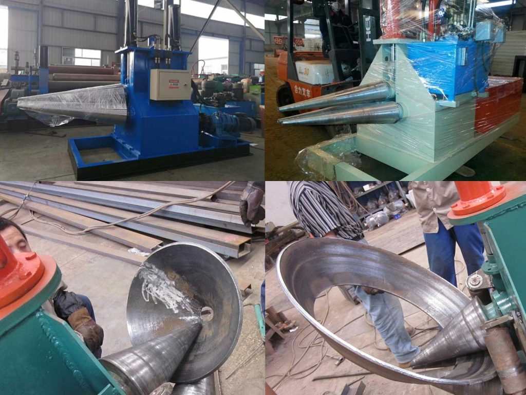
- The conical roller method: There are three rollers cone roller, the taper of the cone roller is related to the workpiece, the workpiece and the roller surface basically do not slide; the active roller is the cone roller (usually the upper roller), and the passive roller is a tape. The roller sleeve of the segment, the workpiece, the roller sleeve, and the roller core slide with each other. The greater the number of roller sleeves, the less the sliding of the workpiece and the roller sleeve, and the movement of the fan-shaped steel plate is realized directly by the tapered roller. The cone roller method is the most efficient and cost-effective method and is suitable for single-type and high-volume production.
- Clamping roller method: In general, a four-roller plate bending machine can use a pinch roller method to incline the lower roller and clamp the large end of the workpiece with the upper and lower rollers. Different workpieces can be applied by adjusting the tilt amount and clamping force of the lower roller. The slewing motion of the fan-shaped steel plate around the vertical line passing through a certain point on the bus bar is achieved by the friction force between the pinch roller and the workpiece surface. This method is simple but requires experience, and when the taper is large or the workpiece is thick, often needs to use with the wheel.
The advantage of the non-blocking wheel method is that the edge of the workpiece is not in contact with the stop wheel. The groove can be made first and then rolled. The completeness of the groove has an impact on the welding quality. The wheel method has damage to the workpiece’s groove. Especially for workpieces with large or thick taper, it is very difficult to make a groove on a round workpiece by first forming a groove and then using a groove。
In order to make the first groove and then roll the cone, we designed the following cone device to wind the cone in a roll that is both a rolling cylinder and a cone. According to the taper of the wind turbine tower, a three-stage taper sleeve is designed for the upper roller. The tapered sleeve is fixedly connected with the upper roller by a key. The tapered sleeve is 35mm thick on average. The quenching and tempering processing is matched with the upper roller and the two lower roller surfaces are quenched. In the space between the two rollers, a small clamping roller driven by the cylinder can be set to clamp the workpiece and the upper roller to prevent the workpiece and the upper roller from sliding. As a result of the actual rolling process, the workpieces with a thickness of 26 mm and Q345 have achieved better results due to the smaller workpiece taper without the use of clamping rollers. If the upper roll is also quenched, it will be better to disassemble the sleeve. This is a combination of the cone roller method and the pinch roller method. Because the lower roller is a cylindrical roller and the upper roller is a roller sleeve, the structure is simple and the cost is low.
There are the following in the wheel method
- Set the stop wheel on the upper roll on the overturn side: the stop wheel is installed on the transition section between the upper roll body and the upper roll overturn bearing through axial and radial bearings, and part of the catch wheel is inserted into the tilt stand The limit stop wheel does not rotate with the upper roller. The gear wheel is generally in contact with the small head plate edge of the workpiece, mainly relying on the frictional force between the retaining wheel and the workpiece plate edge to realize the circling movement of the fan-shaped steel plate around the vertical line passing through a certain point on its own bus. This method is applicable to workpieces with small plate thickness, large taper, and small head diameter.
- A stop roller is arranged on the lower roller on the overturned side: the stop wheel is arranged on the two lower roller bearing seats on the overturning side, and the stop wheel is directly fixed together with the upper part of the lower roller bearing seat. The principle of operation is the same as that of the first method. It is applicable to workpieces with large tapers and small head diameters, and the plate thickness is larger than that of the first method.
- Set up the stop wheel on the frame on the overturned side: The stop wheel is bolted to the frame on the overturned side of the four-roller coiling machine, and the upper plane of the stop wheel is slightly higher than the lower bus of the upper roller.
- Set up the stop wheel on the overturning frame: Install the stop wheel on both sides of the upper roller on the overturning frame, and set a short sliding key between the tilt frame and the frame. The above kinds of gears are installed on the overturning side. This is because the size of the overturning frame is small. The overturned side frame is low and the workpieces generally do not interfere with it. The retaining wheel clings to the work roll surface and the taper can be rolled. Larger, smaller diameter workpieces.
- Set the stop wheel on the bed body: the stop wheel frame is mounted on the bed body with the pin, the stop wheel is installed on both sides of the roller, the stop wheel frame can rotate around the pin axis, and the stop wheel can be raised and lowered in the stop wheel frame.
- Set the stop wheel on the rack on the drive side: on the rack on the drive side, there are larger mounting planes on both sides of the upper roll, with optional internal threads, trapezoidal grooves, or Pins, keys, and the like are used to fasten the stop wheel device so that the relative position and direction of the gear wheel device to the work roller can be changed as required.
How to improve the roll cone capability
The four methods of the second, fourth, fifth, and sixth gears in the gear wheel method have two gear wheels, respectively on both sides of the upper roller. When working, the edge of the wheel is against the two gear wheels, and the gear wheel pair on the feed side is Torque is applied to the workpiece. The stop wheel on the discharge side guides the workpiece. Under the action of the wheel force, the workpiece will deviate from its original position. Most of the time, the workpiece contacts only one gear, and the feed wheel on the feed side applies to the workpiece. Torque, the discharge wheel on the discharge side guides the workpiece, that is, the workpiece rotates around the center line, and is blocked by the gear on the discharge side.
The two gears complete the task of guiding and applying the rotational moment. The two gears are better than the one of the gears. The two gears are larger than one gear to apply a turning moment to the workpiece, but the two gears are on both sides of the upper roller. When the small diameter of the workpiece is small, it is not easy to block. To the workpiece. When using two stop wheels, the stop wheel is preferably able to rotate around its own axis and can move up and down along its own axis, which has little wear on the edge of the plate and long quenching life on the surface of the stop wheel. When two stop wheels are used, it is not the friction between the workpiece and the stop wheel that applies the slewing moment to the workpiece.
Instead, the radial force that the workpiece contacts the stop wheel is more direct than the friction force. The efficiency of the force is greater and it is not necessary to multiply the friction. For the coefficient, the farther the stop wheel is from the upper roller, the longer the arm is, and the greater the applied moment of rotation is, the greater the thickness of the conical cylinder is. This also requires a larger diameter of the small head of the workpiece.
In method 6, there are bearing seats at both ends of the gear wheel, which are simply supported beams and have a large bearing capacity. In method 5, the stop gear is a cantilever beam, and the carrying capacity is relatively small. In method 5, the stop wheel is on the bed, and the workpiece and the frame do not easily interfere.TheTheWe used method 6 on a 3-roll Plate Bending Machine to roll a workpiece with a half-width taper angle of 30 degrees. An additional 1 meter high small and large support was placed between the blocking wheel and the rack mounting plane to position the stop wheel in the axial direction. In-depth work roller surface, to avoid the workpiece and wide rack interference.
Sometimes the workpiece is a flat plate, when the stop wheel cannot reach the workpiece, the workpiece can be bent first, or the stop wheel can be moved downwards to solve the problem. The disadvantage of the stop wheel method is damage to the edge of one end of the workpiece. The stop wheel can rotate around its own axis and can move up and down along its own axis. The surface of the stop wheel can be quenched. This can reduce the damage to the edge of the plate.
When possible, the distance between the stop wheel and the upper roller can be increased. Reducing the force of the stop wheel and the workpiece can also increase the force on the thick workpiece, which requires that the longer end of the plate be pre-bent.In the roll cone process, friction and friction coefficient are very important factors. In the case of the previous non-blocking wheel method, better results can be achieved without the use of clamping rollers, possibly because the friction coefficient of the workpiece is different between the upper roller and the lower roller.
When a certain unit rolled up a large-scale 40-50mm thick high-strength steel cone on a three-roll Plate Bending Machine, the problem occurred that the gear mounting bolts on the transmission side frame were all cut off.
The work was in a standstill and analyzed by our site. Judgment of experience may be caused by resonance. It is recommended to add a little lubricating oil between the workpiece and the driven roller to change the friction coefficient and change the frequency of vibration. This not only solves the problem but a thicker workpiece can also be rolled because of lubrication. The oil will also simultaneously lower the load that causes the workpiece to wrap around the plumb line passing through a point on its own bus. It should be noted that after the roll is finished, the lubricant on the workpiece should be handled without affecting the welding quality.
Rolling force estimation
How much force the various methods required for different workpieces requires both experience and rough calculations. From the above analysis, it can be seen that only a one-stop wheel is used to apply the slewing moment to the workpiece, and the load cannot be evenly divided on the two-stop wheels. . A unit uses method 6 to roll the shell cone of the blast furnace on the coiling machine. Because the strength of the connecting bolts at the upper and lower sides of the transmission side rack is not enough, the connecting bolts are broken during the rolling cone, and the connection between the racks is improved. Successfully rolled. The first type of gear is mainly based on the friction between the stopper and the workpiece. The positive pressure on the stopper is several times that of the friction. It is easy to damage the large workpiece. According to the size of the workpiece, different requirements choose the appropriate method.