The wind tower has developed rapidly in recent years, and we have found its tall figure in many places. Well, behind the fact that they provide us with clean energy, we should ask the question, why does it need to be so high?
This is a question about the actual design of the wind towers themselves.
Why do wind towers need to be so high?
Details get complicated, but their overall design concept is basic. The energy produced by a wind turbine is proportional to the size of the blades mounted around the rotor. The longer the blades, the higher the power output. The generator is mounted over a steel tower, the height of which determines the maximum blade length and, therefore, the amount of energy that can be generated by the wind the system captures.
The power of wind turbines is continually increasing, which means the size of the towers—height, diameter, and plate thickness—is growing too. Because of their large size, rolled sections can’t be kept in stock easily. For this reason, wind tower production requires a lean, continuous-flow environment, with sections moving quickly between cutting, rolling, welding, and then painting.
Steel tower/concentric cone
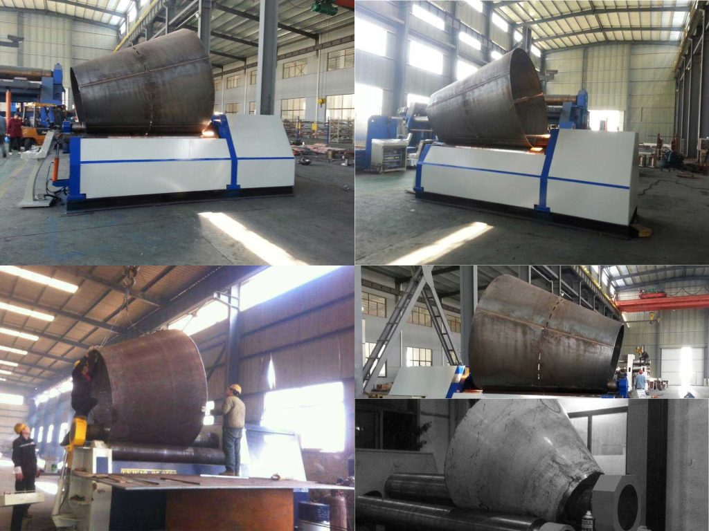
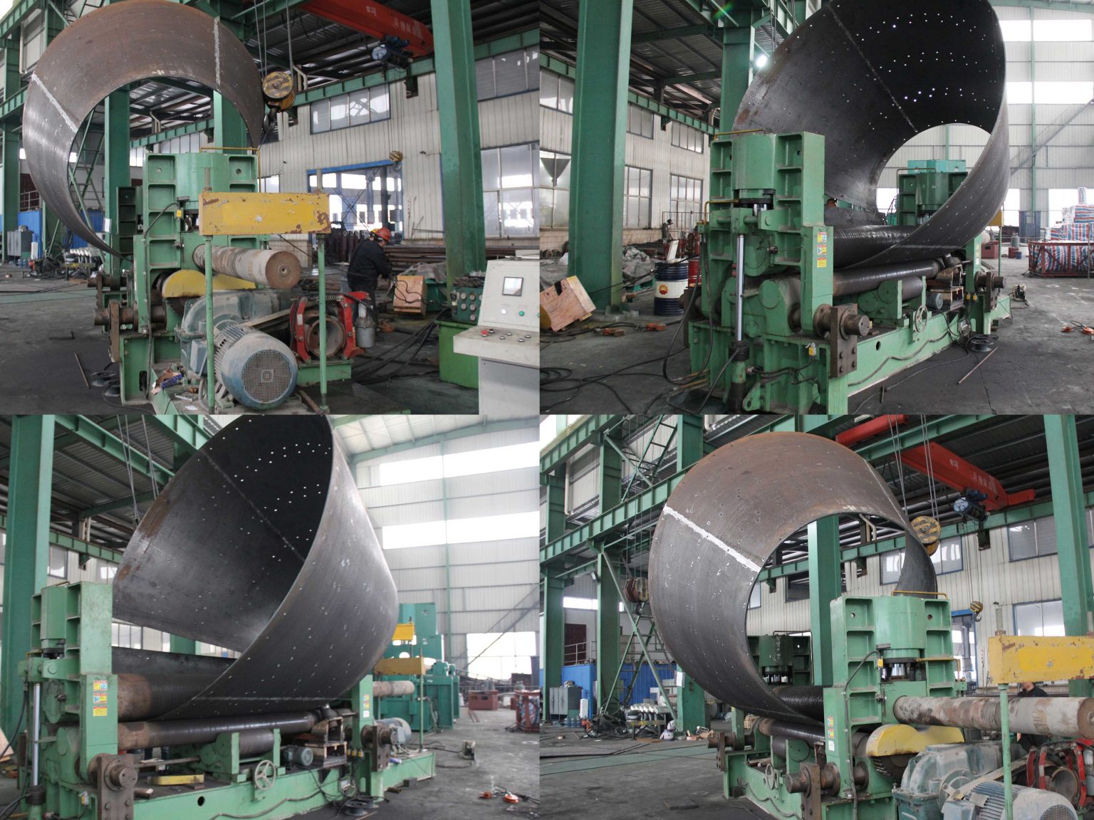
The steel tower is formed in concentric cones primarily by either rolling the plate in a cone rolling machine(bending rolls), or the precision rolling process forms the massive sections. Because of their high volume and speed requirements, most wind tower production facilities use fixed-geometry, four-roll systems. Fixed-geometry machines have lower rolls that are positioned in a certain way for a given design. They can be moved up and down, either with a linear slide (straight motion) or a swing arm (curved motion). On a fixed-geometry machine, the lower rolls always move up and down in the same pattern. The rotating top roll cannot be repositioned. Though fixed-geometry machines may have less flexibility than variable-geometry designs, they do offer high precision and speed, which are paramount for a wind tower operation.
3-roll variable-geometry plate bending machine or top roll variable-geometry bending rolls may be an option.

The 3-roll variable-geometry bending rolls allow operators to move the lower rolls horizontally and the top roll vertically, and the top roll variable-geometry bending rolls allow operators to move the top roll horizontally and vertically. The variable-geometry machine allows operators to move the rolls to adjust for this increased thickness. In many of these cases, the higher versatility of the variable-geometry machines compensates for their slightly lower output rate.
In the left picture, we can observe a top roll variable geometry plate rolling machine bending the formed cone, in fact in China where wind towers are more popular, most of these steel tower manufacturers do not buy expensive four-roll machines, Instead, a Top Roll Variable Geometry 3 Roll Bending Machine was chosen.
Correct Crowning for a top roll of the bending rolls
What is the crowning of the bending rolls
To comprehend the process of “crowning” in metal fabrication, one must first understand the concept of “deflection.” Deflection is an engineering term used to describe the amount of deformation or displacement that occurs in a structural element when it is put under a load.
Fabrication equipment such as press brakes and plate rolls can likewise flex or deform slightly in the middle of the ram or roll, where the tool is less supported than at the ends. Even though the machine is applying pressure to form the part, the part is likewise putting pressure back into the machine, which becomes greater towards the center. This temporary deflection of the tooling while under pressure can be transferred permanently into the bend or roll of the finished workpiece.
In the case of a plate roll, a “barrel effect” in the rolled part is the likely outcome, where the workpiece has a larger diameter in the middle than at the ends. (Note that overcompensating for deflection can cause another type of deformation, an “hourglass effect” in the finished part where the material is drawn tighter together in the center than the ends.)
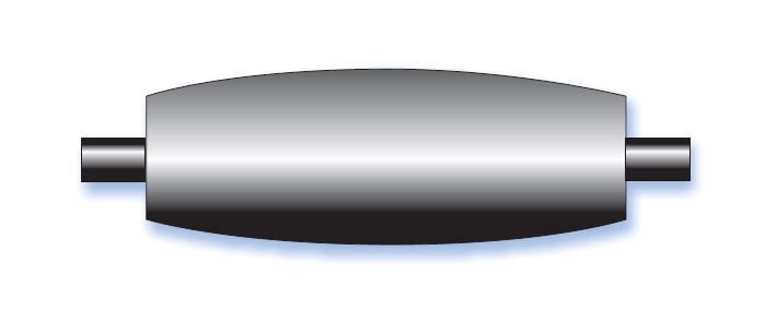
Deflection occurs in fabricating machines like brakes and plate rolls because they can’t apply equal tonnage across the length of workpieces. To adjust for this, the process of crowning was developed, which traditionally involves raising the middle of the ram or roll to create a high point (or crown) in order to compensate for the diminished tonnage in the center.
Correct Crowning
The precision of a rolled conical tower section is measured by the size of the flat ends at the leading and trailing edges, after pre-bending; the level of barrel or hourglass effects over the full range of thicknesses; and the overall consistency of the cone angle.
The barrel and hourglass effects usually occur because of either improper crowning or an undersized machine. A crowned roll is designed to work with a specified thickness range. If the material is too thin for the roll’s crown, the roll doesn’t deflect quite as much. So it’s bent a bit too much in the center, producing a rolled section with a slight hourglass shape. If the material is too thick, the roll will deflect too much, so it will bend less in the center than at the ends. In this case, the finished product looks a little like a barrel. An operator can shim either at the two ends (for thicker material) or at the center (for thinner material) to eliminate these effects. But this can slow production significantly, which can be a burden, especially for a wind tower manufacturer.
A machine crowned for 1-in. material consists of rolls with the middle slightly larger in diameter than the ends, to compensate for the deflection the machine will experience when a 1-in. plate is put into the machine. The diameter difference is slight, measured in thousandths of an inch. This bulge, or crown, counteracts the material deflection as it forms up through the rolls.
Precision rolling machines can be designed with the side bending rolls positioned as close as possible to the lower center roll (pinch roll)— almost touching, in fact. The top roll, pinch roll, and side rolls all are larger than on conventional rolling machines. This added mass guarantees reduced deflection under load. The larger rolls require less crowning, so they are able to roll a wider range of thicknesses. In fact, rolls that are 20 percent larger than normal can help minimize deflection by nearly 100 percent, which means operators don’t need to use shims to adjust for various plate thicknesses.
Conical Considerations
Because wind towers are conical, rolling machines must tilt rolls slightly to put more pressure on one end of the roll than the other. To maintain consistency of the wind tower’s conical angle, and to prevent off-center loading, the rolls’ degree of tilt must be preset automatically and kept constant throughout the rolling cycle.
This constant tilting, or balancing, ideally is accomplished with numerical control, which can send continual adjustments to hydraulic proportional valves on either end of the rolls. Some machines have four independent bearings supporting each roll, so that the roll tilt can match precisely the angle required by the conical wind tower sections while maintaining full support, even in the tilted orientation. Electronic balancing systems can keep tolerances at less than 0.008 in., as demanded by precision wind tower work.
Unlike other cone applications, tower cone sections are only slightly conical. Conical rolls aren’t necessary. In conventional cone rolling, the contrast die—a wheel or hardened steel piece mounted to the machine frame—contacts the small-diameter portion of the cone, so it can be rolled slower than the large-diameter portion. However, because wind tower sections are only slightly conical, the plate never comes in contact with the contrast die. And since the sections are formed with a cylindrical rolling operation, there is also no damage to their beveled edges from friction.
Works Cited
- “Rolling for wind”, the fabricator, 08 Aug. 2022, https://www.thefabricator.com/thefabricator/article/bending/rolling-for-wind
- “what is plate roll crowning”, Revolution Machine Tools, 08 Aug. 2022, https://www.rmtus.com/what-is-plate-roll-crowning