The apron feeder can convey materials horizontally or at an inclined angle, so it is widely used in metallurgy, the chemical industry, building materials, mining, and electric power industries.
Heavy-duty apron feeders are basically made of metal materials and consume a lot of power. Therefore, accurate force analysis is very important for power calculation and component selection during design. This paper focuses on the calculation method of the pressure of the silo on the feeder and gives the design, calculation, and selection methods of the heavy-duty apron feeder in detail.
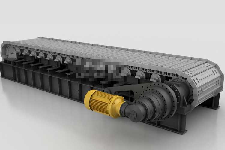
Structure and working principle of heavy-duty apron feeder
The heavy-duty apron feeder structure can be equipped with a skirt and hopper assembly according to customer needs.
Top five main structure
- Powertrain: including motor, planetary gear reducer, coupling, etc.;
- Drive shaft assembly: including drive shaft and drive sprocket, etc.;
- Carrying assembly: including traction chain rail and slot plate, etc.;
- Tail shaft assembly: including tail shaft, guide wheel and tension cylinder, etc.;
- Frame: It is welded by steel plate and section steel, which is the carrier of the whole equipment.
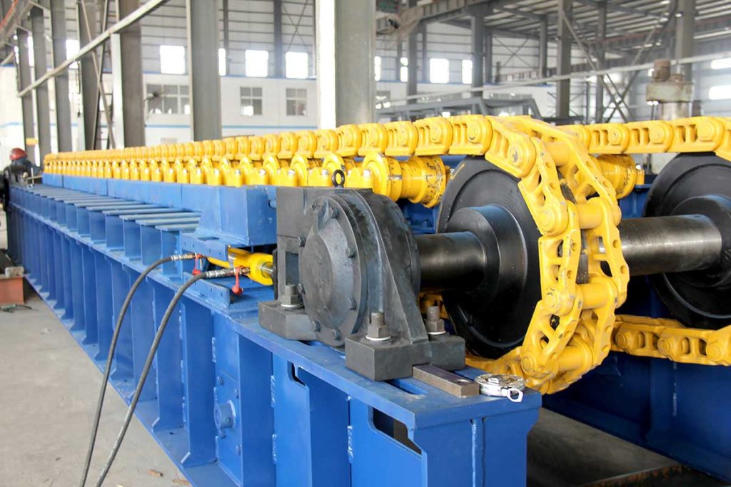
Working principle
The motor drives the planetary gear reducer to drive the drive shaft and the drive sprocket to rotate, and the drive sprocket rotates to drive the chain rail joints to drive the load-bearing groove plate to achieve the purpose of transporting materials.
The design calculation of heavy-duty apron feeder
Main parameters
The input parameters are directly provided by the customer or determined by the customer’s complete equipment process, mainly including processing capacity, the center distance between the drive shaft and the tail shaft, material accumulation density, equipment installation inclination angle, maximum particle size of the material and relevant information of the silo.
- The effective width of the groove plate
- Chain track running speed
- Drive shaft speed
- Loading material length
- Transmission ratio
Calculation of driving power of heavy-duty apron feeder
The running resistance of heavy-duty apron feeder is divided into two categories according to the cause: friction and slope resistance. Friction force includes the friction resistance caused by the self-weight of the moving parts of the apron feeder, the friction resistance caused by the positive pressure of the material, the friction resistance of the conveying material and the skirt plate, the friction resistance of the material guide device and the additional resistance.
Four major resistances in the operation of heavy-duty apron feeders:
The friction of moving parts
The friction force of the moving parts includes the friction resistance of the upper and lower branch support wheels and the chain rail slot plate device in the support device. Although the upper and lower branch support wheels and the chain rail slot plate are not completely uniform within the range of center distance, it can be approximated when calculating Uniformly distributed load within the range of center distance.
Frictional resistance due to positive pressure on the material
The material layer thickness of the material on the groove plate is uniform, so the positive pressure of the material self-weight acting on the groove plate is also uniform, and the pressure generated by it finally acts on the upper branch support spokes.
Friction resistance of transported material and skirt
The material between the channel plate and the skirt plate will form a material flow with a cross-section approximately rectangular, which has side pressure on the skirt plate when the material runs with the channel plate. There will be friction resistance between the material and the skirt.
Frictional resistance of the material guide
Under normal circumstances. Heavy-duty apron feeders will be installed under the silo, and the silo will generate a certain pressure on the running parts. Thus forming frictional resistance. Also known as the resistance of the material guide.
The main pressure acting on the apron feeder is related to the nature of the material, the depth of the material in the silo, and the structure of the silo. Usually, according to the depth and hydraulic radius of the silo, the silo is divided into the shallow silo and deep silo. When the depth of the silo is greater than 10 times the hydraulic radius, it is a deep silo, otherwise, it is a shallow silo. Loose materials have certain fluid characteristics. At the same time, due to the internal friction between the loose materials, when the materials are accumulated in the silo, the pressure of the loose materials on the discharge port cannot be calculated completely according to the static pressure of the fluid, nor can it be completely calculated according to the static pressure of the fluid. Calculated by weight of bulk material. This requires the calculation of the difference between deep and shallow bins based on the height of the bin and the hydraulic radius of the loose material.
Additional resistance
The additional resistance is due to the friction in the chain link of the chain rail, the friction between the chain rail and the sprocket and other comprehensive factors to form resistance when the chain is running. According to experience, it is generally 5% to 10% of the main resistance.
Ramp resistance
Heavy-duty apron feeders are installed at an incline. Loading material creates ramp resistance.
Chain track tension calculation
During the operation of the apron feeder, the force on the chain rail changes periodically. When designing and calculating the chain rail, it should be calculated based on the maximum tension of the chain rail.
- The initial tension keeps the chain track moderately tensioned. Ensure the normal and reliable operation of the apron feeder. Based on experience. The ratio of the maximum sag of the heavy-duty apron feeder to the span of the branch support h/a is 0.05, and the initial tension should take the larger value of the bearing branch and the return branch.
- Chain track dynamic load tension: Due to the polygonal effect of the sprocket, an additional dynamic load tension is generated on the chain track.
Equipment selection
According to the calculation, it is easy to select a reasonable and economical model for the chain rail, sprocket, drive motor and reducer of the apron feeder.
Selection of chain rail and sprocket wheel: after calculating the tension of chain rail according to the above, the breaking tension can be selected according to the chain and should not be lower than 5 times of the working tension. Considering the large moment when the heavy-duty apron feeder is started, the humidity of the material and other factors, the track chain rail is generally selected according to the breaking force of the chain rail link not less than 6 times the working tension. When the chain rail of the heavy-duty apron feeder is selected, the sprocket can be determined according to the pitch of the chain rail and the number of teeth of the sprocket. The rails are all in contact, so that the service life of the sprocket is doubled;
Selection of motor and reducer: The selection of the driving motor should be based on the calculated power. At the same time, considering that the apron feeder is a constant torque device, a frequency conversion speed regulation motor is generally used; this can not only adjust the speed at any time according to customer needs, but also Ensure that the apron feeder starts under heavy load. When using frequency conversion speed regulation, try not to lower than 40% of the frequency at the set speed. The selection of the reducer should be considered to meet the matching of output torque and load torque, and the matching of input speed and driving motor speed.
Final Words
To sum up, when the customer’s demand or the main parameters are fixed, the design and calculation of the heavy-duty apron feeder can be carried out according to the above method, and its power can be determined, and the appropriate reduction ratio, chain-rail pitch, etc. can be selected; in this way, it can be rea
Read More: Variable rate feeder Wikipedia