What is a screw conveyor?
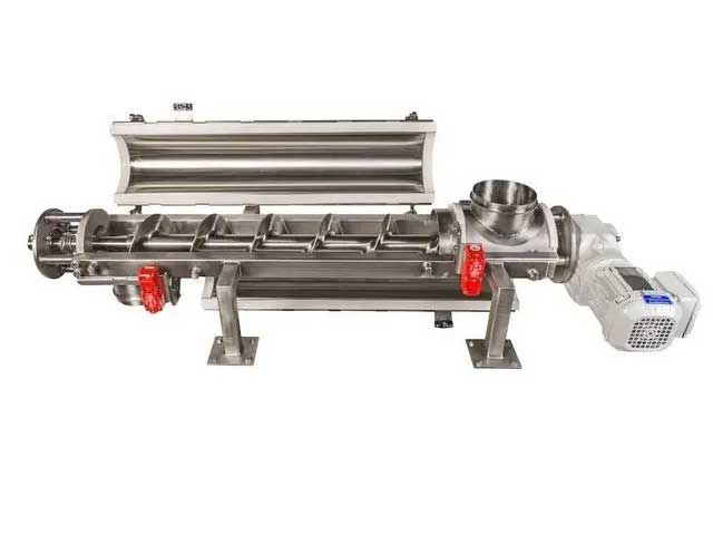
The screw conveyor is used for the continuous conveying of bulk materials. It consists of a spiral body formed by one or more sets of helical blades fixed on the tube shaft and a fixed trough. The spiral rotates in a fixed trough.
The bulk material fed into the trough rotates together with the helical blade in the trough and is prevented by the friction force on the trough wall. During operation, the helical blade pushes the bulk material to move axially. Bulk materials can fall from a suitable opening at the bottom of the tank or be output from the end of the tank.
Conveyor calculation principle
The driving power required by a conveyor is related to the conveying capacity it can achieve, but it is also related to the working conditions and the nature, structure, and calculation parameters of the conveyed materials.
Symbols and units
- A: The axial projected area of the spiral, in square meters (m2);
- D: The nominal diameter of the conveyor screw, in meters (m);
- FH: material running resistance (main resistance), the unit is cattle (N);
- FN: no-load running resistance (additional resistance), in cattle (N):
- Fst: Tilting resistance, in cattle (N);
- g: gravitational acceleration, in meters per square second (m/s2);
- H: lifting height, the unit is meter (m);
- Im: mass conveying capacity, in tons per hour (t/h);
- Iv: Volume delivery, in cubic meters per hour (m3/h);
- L: conveyor length, in meters (m);
- n: Conveyor speed, unit is revolution per minute (r/min);
- P: total driving power of the conveyor shaft end, in kilowatts (kW);
- PH: the power required for the material to run, in kilowatts (kW);
- PN: the driving power of the conveyor when it is running without load, in kilowatts (kW);
- Pst: tilt power, in kilowatts (kW);
- S: screw moment, the unit is meter (m);
- ⅴ: conveying speed of the conveyor, in meters per second (m/s);
- λ: running resistance coefficient;
- Φ: filling factor;
- ρ: Bulk density, unit is ton per cubic meter (t/m3);
- N: motor power;
- ξ: motor power reserve coefficient;
- η: Motor transmission efficiency.
Delivery capacity
The initial data for calculating the volumetric conveying capacity and mass conveying capacity of the conveyor are the spiral axial projected area A of the conveyor, the conveying speed v, and the filling coefficient Φ of the conveyor trough.
The mass delivery Im is the maximum mass throughput completed by the conveyor under rated conditions. The throughput depends on the size of the filling coefficient Φ. The filling factor depends on the friction of the material being conveyed and its adhesion, the pitch, and the inclination of the conveyor axis. The filling factor is generally taken as:
- a. For materials that are easy to flow and have almost no abrasiveness (such as flour and grains), take Φ=0.45;
- b. For slightly abrasive bulk materials (such as salt, sand, coal) that are granular to small lumps, take Φ=0.33;
- c. For bulk materials (such as slag, gravel, ore) that are highly abrasive and erosive and have a high bulk density, take Φ=0.15.
In the following cases, the value of Φ should be reduced:
- a. When the pitch is particularly large, the Φ value is reduced by 10%;
- b. For every 1° inclination of the conveyor axis, the Φ value will decrease by about 2%;
- c. If it is necessary to charge the material at the intermediate support, the value of Φ is reduced by 10%.
The peripheral speed of the conveyor is not allowed to be too large, otherwise, the conveyed material will be affected by the centrifugal force and the conveying process will be affected. Therefore, the maximum rotational speed max depends on the nominal diameter D of the screw.
The required minimum screw nominal diameter of the conveyor depends on the required productivity of the conveyed material and the particle size of the bulk material. For bulk materials, the nominal diameter D of the spiral should be at least 10 times the maximum side length amax of the particle. If the content of large particles is small, it is also allowed to choose a smaller nominal diameter of the spiral, but at least D≥4amax.
Motion resistance of screw conveying
The resistance to be overcome by the rotation of the conveying screw and the forward movement of the material includes:
- a. Material running resistance FH;
- b. No-load running resistance FN;
- c. Tilt resistance Fst
The above three resistances are all resistances related to friction and inclination that the conveyor drive must overcome in order to make the material move at the loading place.
Tilt resistance is not present in all installations and is a function of line tilt. Of all resistances, only slope resistance can be accurately calculated.
Motion resistance of screw conveying
The resistance to being overcome by the rotation of the conveying screw and the forward movement of the material includes:
The total driving power of the conveyor shaft end
Calculation of the total driving power of the conveyor shaft end is calculated according to the following formula. P=PK+Pn+Pst