Heavy-duty apron feeder is a continuous transportation machine widely used in mines, metallurgy, building materials, ports, coal, and chemical industry, and mining enterprises. The heavy-duty apron feeder is mainly used to continuously and evenly supply and transfer various large and heavy bulk materials from the storage bin or transfer hopper to the crusher, batching device, or transportation equipment. It is one of the important and indispensable pieces of equipment in ore and raw material processing and continuous production process.
As an interface between trucks or plant stockpiles and the processing system, Apron Feeders provide steady, controlled feed for downstream processing in cement and mining applications. Read More: Apron Feeders, Everything You Need to Know, Best Guide 2023
The working principle of an apron feeder is straightforward: a continuous steel belt or chain is positioned beneath the feed hopper and supported by steel rollers or sprockets. As material is drawn from the hopper and onto the apron feeder, the pans move along the feeder’s length, conveying the material to its intended destination.
The speed of the apron feeder is regulated to control the flow rate of material, and the height of the material discharge point can be adjusted to control the flow of material into the processing equipment. The feeder can also be fitted with a variety of liners, such as cast manganese or rubber, to protect the pans and extend their lifespan.
Working principle of heavy apron feeder
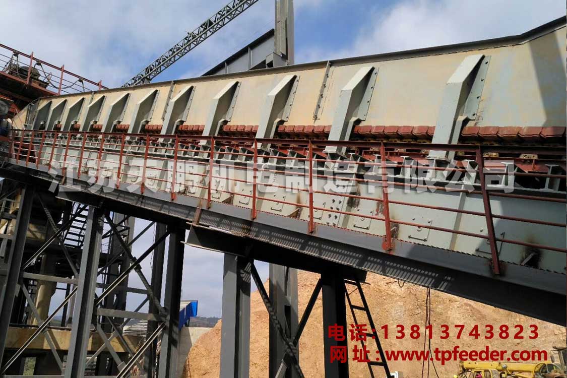
The heavy-duty apron feeder adopts a high-strength bulldozer die-forged chain with a pitch of 216 as the traction part. The two chains bypass a pair of driving sprockets installed at the head of the body and a pair of tensioning wheels at the tail of the body to form a closed shape. In the circuit, each chain link of the two rows of chains is equipped with overlapping, heavy-duty conveying troughs to form a continuous conveying line capable of carrying materials.
The weight of the heavy-duty apron feeder and the weight of the material is supported by two rows of chain rollers installed on the body, and the lower part is equipped with supporting rollers to support the empty conveying trough.
The transmission system of the heavy-duty apron feeder is connected to the reducer through the AC variable frequency speed regulating motor, and then the expansion sleeve is directly connected with the driving device to drive the carrying mechanism to run at a low speed. The materials unloaded from the tail hopper are discharged along the conveying line in front of the machine body, so as to achieve the purpose of continuous and uniform feeding to the working machinery below.
Top 7 Components of Apron Feeder
An apron feeder consists of several key components that work together to efficiently convey material. These components include:
- Feed hopper: This is the starting point for material to be fed into the apron feeder. The hopper is typically positioned above the feeder and can be filled with material using a front-end loader or other equipment.
- Drive system: The drive system provides the power needed to move the apron feeder pans. It typically consists of a motor, reducer, and chain or belt that runs along the length of the feeder.
- Apron pans: The apron pans are the key component of the apron feeder. They are made of heavy-duty metal and are positioned beneath the feed hopper. The pans are connected to the drive system and move along the feeder’s length to convey the material.
- Sprockets or rollers: The sprockets or rollers support the apron pans and allow them to move smoothly along the feeder’s length. They are typically made of steel and are positioned at regular intervals along the feeder.
- Skirts: The skirts are used to contain the material on the apron feeder and prevent it from spilling off the sides. They are typically made of steel or rubber and are positioned on either side of the apron pans.
- Discharge chute: The discharge chute is the end point for the material conveyed by the apron feeder. It is typically positioned above the processing equipment and can be adjusted to control the flow of material into the equipment.
- Lining: The apron feeder pans and discharge chute can be lined with various materials, such as cast manganese or rubber, to protect them from wear and extend their lifespan.
These components work together to ensure that the apron feeder can effectively and efficiently convey material from the feed hopper to the processing equipment.
Heavy Duty Apron Feeder Components
The heavy-duty apron feeder consists of the following seven main parts, which are described as follows:
Transmission
The variable frequency speed regulating motor is directly connected to the shaft-mounted reducer through the elastic pin coupling, and the main drive shaft is directly connected in series with the hollow output shaft of the reducer, and connected through the locking disc (expanding sleeve). Since the reducer adopts a suspended shaft-mounted structure, the transmission device is suspended as a whole. When it is installed in place, the reducer bracket can be simply connected to the main machine frame or a simple arm-type support can be set under the reducer bracket to connect to the ground. The seat is made according to the site conditions. The installation method of the transmission device is divided into left-mounted and right-mounted drives. Looking at the direction of material movement, when the transmission system is installed on the right side, it is called the right transmission, and on the left side, it is called left transmission.
Head wheel and tail wheel
The driving sprocket is made of multi-tooth alloy cast steel, and the tooth profile is hardened by surface quenching, which has good strength and wear resistance. The tensioner adopts a toothless structure and hardening treatment process on the outer tread surface, which achieves the purpose of reducing the vibration during operation and the wear of the traction chain, and affects the smooth operation of the whole machine. The drive shaft and tension shaft are made of 40Cr forged steel and quenched and tempered heat treatment. The main bearings are all self-aligning roller bearings, the bearing housings are made of cast steel, and the two shaft ends are sealed with a rubber skeleton oil seal structure, which will not leak oil for a long time, with good lubrication and sealing performance, long service life, small running resistance, and Easy maintenance features. The tail adopts a butterfly spring tensioning mechanism, which can easily and effectively control the pretension of the traction chain and adjust the deviation of the carrying mechanism.
Chute assembly
The heavy-duty apron feeder adopts the bulldozer crawler chain with a standard pitch of 216 as the traction chain (commonly known as the tank chain). The breaking force of a single chain is greater than 125t, the service factor is greater than 6-8, and the tensile strength is sufficient. It can be used for a long time under normal maintenance conditions without replacement. The conveying trough for loading materials is welded into a rigid trough by the bottom plate, inner and outer plates, reinforcing beams, and supporting plates. It has the characteristics of wear resistance and impact resistance, and the overlapping parts are transitioned by arc-shaped plates without gaps so that no matter whether the material is conveyed horizontally or inclined, there will be no material leakage. Sex for connection.
Drag chains generally do not require lubricating oil, but it is allowed to manually drip oil between the chain nodes and chain plates to reduce wear and resistance.
Chain rollers, lower rollers
The supporting rollers adopt cast steel rollers and roller bearing structures, and the ends of the two shafts adopt rubber skeleton seal oil seal structures, which will not leak oil for a long time, so they can withstand the heavy pressure of the carrying mechanism for a long time without replacement. Both sides of the rollers are equipped with ribs, which can effectively control the deviation of the conveyor chain.
The lower support roller is used to support the return of the carrying mechanism (circular closed circuit). It also adopts cast steel rollers and roller-bearing structures. The two shaft ends adopt rubber skeleton seal oil seal structures, which will not leak oil for long-term work. The lower support roller has a rib on one side, which can effectively control the deviation of the conveyor chain. Both the supporting rollers and the lower supporting rollers are rigidly fixed on the machine body. The rollers of this machine are designed to be arranged in two rows. Under normal maintenance conditions, the service life of the rollers and the lower supporting rollers is more than 2 years.
Frame
The machine frame adopts an integrally welded structure, and many parts have been strengthened to fully increase the rigidity of the machine body and the ability to withstand impact loads. A special assembly welding process is adopted for the plane where the bearing seat is installed, which improves the assembly accuracy. Due to the compact structural arrangement, the lateral dimension of the machine body is smaller than that of similar products of the same model. (
Guards and discharge funnels
The guard plate is composed of a pillar and a hopper, which are bolted together and supported on the frame. The inlet at the tail is connected with the silo. The discharge funnel is a steel plate structure, which is connected with the guard plate to form a closed material guide protection system. Install wear-resistant linings on guards and discharge funnels. Due to the different working conditions of each user and to reduce the purchase cost of the user, generally, no wear-resistant liner is provided, and the user is self-made.
Read More: Feeder Wikipedia