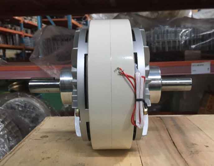
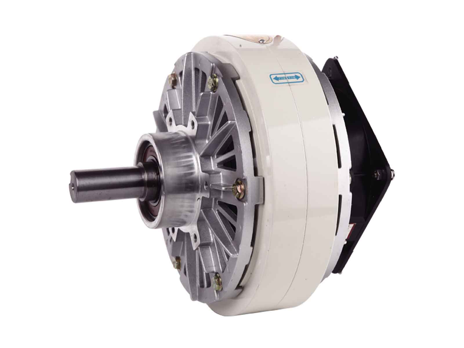
Magnetic particle brakes are electromagnetic devices that are used to control the rotational speed of machine components. In order to ensure that the magnetic particle brake provides adequate and reliable control, the required braking torque must be calculated accurately.
Understanding the Basics: Torque and Friction
Before diving into the calculation process, it is crucial to understand the basics of torque and friction. Torque is a measure of the force applied to an object to rotate it around an axis. In the case of a magnetic particle brake, torque is the measure of the force applied to the machine’s rotating component to bring it to a stop or control its speed.
Friction is the force that resists the motion of one surface or object moving against another. When the rotating component of a machine comes to a stop, it experiences friction with the brake pad. The torque required to bring it to a stop is directly proportional to the amount of friction between the component and the brake pad.
Calculating the Required Braking Torque
The required braking torque for a magnetic particle brake is determined by several factors, including the machine’s weight, the rotational speed of the component, and the coefficient of friction between the component and the brake pad. The general formula to calculate the required braking torque is as follows:
T = (I x w^2 x r) / (2 x f )
Where:
T = Required Braking Torque (in Nm)
I = Moment of Inertia (in Kg m^2)
W = Angular Speed (in radians per second)
R = Effective Radius of the Brake Drum (in meters)
f = Coefficient of Friction (-)
The Moment of Inertia is the physical quantity that measures the object’s resistance to rotational motion. It depends on the object’s mass distribution and the axis of rotation. The effective radius of the brake drum is the average distance between the center of the component and the brake pad. The coefficient of friction is a value between 0 and 1 that represents the ratio of the force required to maintain motion between two surfaces to the normal force holding them together.
Examples of Coefficients of Friction for Different Materials
| Material | Coefficient of Friction |
|---|---|
| Aluminum | 0.3 – 0.5 |
| Cast Iron | 2.1 – 3.0 |
| Copper | 0.15 – 0.35 |
| Stainless Steel | 0.4 – 0.6 |
| Tin | 0.4 – 0.6 |
(Source: Adapted from https://www.engineeringtoolbox.com/friction-coefficients-d_778.html)
Steps to Calculate the Required Braking Torque

To calculate the required braking torque for the magnetic particle brake, follow these steps:
- Determine the Moment of Inertia of the rotating component. This value depends on the component’s mass distribution and the axis of rotation.
- Measure the angular speed of the component in radians per second.
- Determine the effective radius of the brake drum by measuring the average distance between the center of the rotating component and the brake pad.
- Determine the coefficient of friction between the rotating component and the brake pad by referring to the Table above or performing your own tests by using method ASTM G115 method.
- Plug the values into the formula:
T = (I x w^2 x r) / (2 x f )
- Calculate the required braking torque in Nm.
Conclusion

Calculating the required braking torque for a magnetic particle brake is essential to ensuring that the brake can adequately control the motion of the rotating component. By understanding the basics of torque and friction, and using the formula we discussed, it’s possible to determine an accurate estimate and ensure that the brake is appropriately sized for the application. It is crucial to ensure the factors consider, e.g., Moment of Inertia, Angular Speed, Effective Radius, and Coefficient of friction are measured accurately, and the formula applied correctly. Calculating the required braking torque for a magnetic particle brake is critical to ensure a safe and reliable operation of the machine.
