The working principle of magnetic particle brake
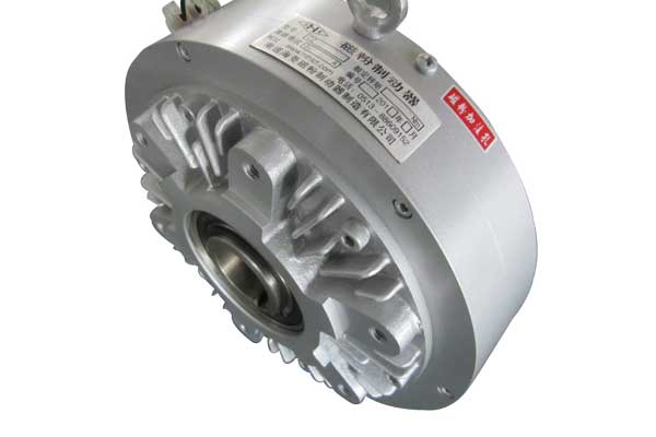
Before explaining the function of the circuit, let’s take a look at the working principle of the magnetic powder brake:
- The magnetic particle brake is a new type of transmission element that uses magnetic particles as the medium and forms a magnetic powder chain to transmit torque under the condition of electrification. It is mainly composed of an inner rotor, outer rotor, excitation coil, and magnetic particle.
- When the coil is not energized, the active rotor rotates. Due to the centrifugal force, the magnetic particle is thrown on the inner wall of the active rotor. There is no contact between the magnetic particle and the driven rotor, and the active rotor runs idly.
- After the DC power supply is turned on, an electromagnetic field is generated, and the magnetic particle of the working medium forms a magnetic particle chain under the action of the magnetic force line, which connects the inner rotor and the outer rotor, so as to achieve the purpose of transmitting and braking torque.
Circuit function
The torque of the magnetic particle brake has a linear relationship with the magnitude of the excitation current, and the magnitude of the braking torque can be adjusted by changing the excitation current. Therefore, the circuit in this example controls the torque by changing the current of the magnetic particle brake constant current source control circuit through the input PWM signal.
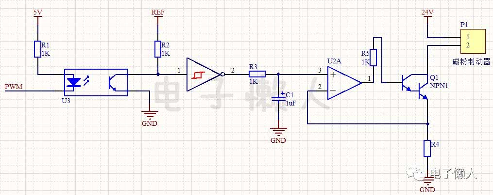
Circuit Breakdown
In this example, the signal direction of the circuit has only one direction. Along the signal line, the whole circuit can be divided into the optocoupler isolation part, the PWM signal inversion amplification and filtering part, and the constant current source circuit control part of the magnetic powder brake.
The working process of the whole circuit
The circuit of this example is a small unit circuit in the tension controller based on an embedded microprocessor. Use the pulse width modulation (PWM) function of the microcontroller to output the PWM signal.
The microcontroller sends the PWM signal to the optocoupler U3 isolation output. The output of the optocoupler uses a reference voltage as a pull-up. After the optocoupler is output, it is inverted by the NOT gate, filtered by the resistor R3 and the capacitor C1, and then output to the non-inverting terminal of the operational amplifier.
According to the basic principle of the virtual short of the op-amp, the voltages of the non-inverting terminal and the inverting terminal of the op-amp can be considered equal. Therefore, the voltage change of the inverting terminal of the op-amp follows the change of the PWM signal voltage. At the same time, the inverting terminal voltage is added to the current sampling resistor R4 to control the current flowing through the magnetic particle controller (or through the Darlington tube).
Notice
Pay attention to the selection of the resistor R4. The resistor R4 should be selected according to the maximum current flowing, and the selected resistor power should meet the conditions.