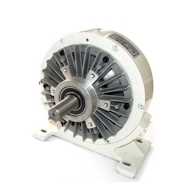
Magnetic particle and hysteresis-type brakes & clutches are used for precision torque & tension control.
- Brakes – When energized, the shaft becomes coupled to the brake’s housing. Typical applications: Brakes can provide adjustable torque for unwinding (payout) of webs, such as wire, foil & paper. Another popular application: Brakes can provide adjustable torque loads to test motors or mechanisms.
- Clutches – When energized, the input shaft becomes coupled to the output shaft. Typical applications: Clutches can produce adjustable torque for rewinding webs.
Both produce smooth, adjustable slip torque, controlled by electrical input. Either type can be used successfully in most applications. But, sometimes one type is much better, due to subtle, but important differences in characteristics.
Two benefits of Magnetic Particle Brakes & Clutches over Hysteresis Brakes & Clutches
- Torque: Magnetic Particle Clutches Torque is higher compared to the same size hysteresis brake. A hysteresis brake with a Ø4-1/2 housing diameter produces 15 lb.-inches torque. A similar-sized magnetic particle brake produces 70 lb.-inches. But, due to the compact size, heat dissipation capability is limited.
- Inertia: Inertia is much lower compared to a hysteresis brake with the same torque rating. For applications with low acceleration, inertia is not important. But, winding systems with indexing motion with fast starts & stops such as high-production electric coil winding requires fast accelerations. The minimal inertia will not add significantly to desired torque & tension, even during the moderately high acceleration.
Two major cons of magnetic particle brakes compared to hysteresis brakes
- Slip torque: Although slip torque is very smooth, there is some slight stick-slip at very low RPM. Avoid applications where smoothness is very important at exceptionally low slip RPM (less than about 10 to 30 RPM). Unwinding a web at 10 RPM may be fine if the web is rigid. If the web is very elastic, sometimes even 30 RPM may be too slow, depending on the web path. If the distance from the payout roll to the first nip roll is long, the web acts more elastically, than if the distance is short. As the nip roll pulls the web material, the web stretches and straightens out, then the brake releases, causing the web to contract & droop. This occurs quite quickly and is observed as a vibration in the material.
- Powder particles wear: Although life is long, avoid constant duty applications with high slip RPM & high torque. The powder particles eventually wear, which causes torque to decrease.
Three benefits of hysteresis brakes over magnetic particle brakes
- Long work life: Hysteresis BrakesTorque is produced without friction, by the interaction of magnetic fields across an air gap. There is no wear and no torque decrease, even at high RPM and high torque. Life is nearly unlimited, except for the ball bearings, which last for years if not abused.
- Heat dissipation: Heat dissipation is superior to magnetic particle brakes & clutches since the size is larger for the same torque. Also, the rotating part that produces the torque & converts the mechanical power into heat (that must be dissipated) is exposed more directly to air, for better cooling.
- The torque is perfectly smooth: The torque produced by the hysteresis process is perfectly smooth, even at near zero RPM.
Two major cons of hysteresis brakes compared to magnetic particle brakes
Cogging
Cogging is a major characteristic to consider and is often misunderstood. Cogging is pulsing output torque. The hysteresis brake (or clutch) shaft tries to lock into preferred positions (between 10 and 30 positions, proportional to the size). Cogging can occur at any RPM.
How to avoid it?
Cogging can be avoided by proper electrical input. To avoid cogging, never drastically decrease input voltage and current while there is no slip (Brakes: zero shaft rotation; Clutches: zero difference between input & output RPM). Decrease voltage and current in a ramp vs. shaft rotation. If the electrical current is ramped down, even very slowly while the shaft is not rotating, the brake (or clutch) will cog.
To de-cog, energized the brake (or clutch) to the previous high input or higher. Then, ramp down the electrical input while simultaneously rotating the shaft through about ½ turn or more. (For clutches, rotate the input & output shafts so there is ½ turn slip.) Manually declogging can be quite an inconvenience.
Shaft inertia
Shaft inertia is much higher, so accelerations must be gradual in winding systems, to avoid stretching or breaking delicate webs & wires.
Works Cited: Placid Industries