Choosing a tension control system can be intimidating, especially with the large array of systems available. Understanding the basic systems, which all comprise some type of brake with open or closed loop control, will aid in your search.
Many material-processing machines use tension control to provide a constant pull of a web or filament through the machine, thereby ensuring consistent product quality.
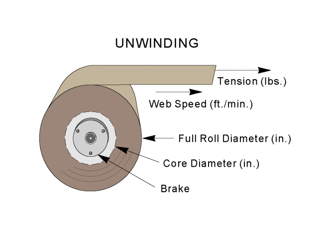
Printing and converting industries account for most web processing applications. In these applications, tension control systems are typically installed at the unwind roll that feeds material into the production machinery.
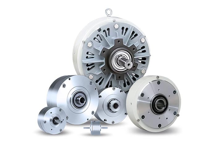
This article covers four types of braking devices commonly used to apply tension in these applications: electromagnetic friction brakes, magnetic clutches and brakes, magnetic particle brakes, and air-actuated friction brakes. For a given application, one of the four types should best meet the application requirements.
Choosing a Brake Type
Selecting the type of brake involves several factors, including application parameters, mounting requirements, type of control system to be used, costs, and in many cases, customer preference. Three operating characteristics are particularly important: torque, thermal horsepower, and revolutions per minute (rpm).
Regardless of the type of brake or control system used, these brake operating factors apply in unwind applications: Maximum brake torque and minimum roll rpm are the case under full roll conditions. As the roll unwinds and becomes smaller, the surface speed at the friction faces increases and required torque decreases proportionately, as does roll inertia. The brake’s torque output also decreases as roll size decreases. However, heat dissipation is constant over the whole range of slip speeds, from full roll to unwound core.
Electromagnetic Clutch-Brakes
An electromagnetic friction clutch brake typically consists of two basic parts: a rotating armature and a stationary magnet assembly with an electric coil.
The armature and magnet have mating friction faces. Current applied to the magnetic coil causes a magnetic field that pulls the rotating armature and stationary magnet into contact. The resulting friction between the faces slows the rotation of the shaft on which the unit is mounted. Adjusting the amount of current supplied to the coil provides proportionately more or less braking.
Electromagnetic units are available as brakes or clutches, and the operating principle for both types is the same.
The amount of running torque and thermal capacity of an electromagnetic brake depends on the number of armature discs and magnets in the unit. Running torque capacities vary with different manufacturers but typically range from about 0.5 to more than 400 lb-ft. Sizes range from 1.7 through 20 in. dia, and thermal (heat dissipation) capacities generally range from 0.02 to about 6.0 hp.
While the brakes are used primarily on unwind applications, electromagnetic clutches are typically used on small rewinders, which require constant web tension on rolls that are being driven to wind material onto them.
Given their moderate torque and thermal capacities, electromagnetic brakes typically are used on unwinds in web processing equipment such as printing presses, coating machines, and small slitters. They best handle light- or medium-weight web materials with tension requirements ranging from 10-80 lb.
Among tension systems, electromagnetic brakes are the most responsive, with activation times in milliseconds. The ability to stop the web rapidly is critical in the event of a jam-up, especially where there is the potential for mechanical damage. A special overexcitation control available for many electromagnetic brakes can further reduce response time. This control sends a momentary high-voltage spike to the brake magnetic coil to build a high-density magnetic flux field almost instantaneously, engaging the brake more quickly at full torque and reducing the time required to stop the roll.
Electromagnetic brakes can remain functional and in control even when operated at near zero currents. This characteristic is useful in a printing application in which the user is running a wide range of tensions for wide webs and also very narrow webs of paper.
Electromagnetic brakes are not recommended for very-low-speed applications, because the metal-to-metal contact tends to create jerkiness (stick-slip phenomenon) when the brake is activated. Therefore, these brakes function best above 50 rpm, to a maximum speed of 1,600 rpm on larger units, and up to 2,300-2,500 rpm on smaller brakes.
Magnetic Particle Units
Electromagnetic (magnetic) particle brakes rely on the magnetic force between two rotating discs, which is transmitted by magnetic particles to produce a retarding force (brake torque). The input shaft and a cylinder form the stationary member; the output shaft and rotor comprise the rotating member. The magnetic particles are dispersed within a gap between the rotor and the cylinder.
Direct current in the coil creates a magnetic field that causes the magnetic particles to attract each other. The particles rubbing against each other cause friction, which resists the relative rotation between the cylinder and rotor. The higher the current flow, the greater the braking torque transmitted.
Torque capacities of these units typically range from about 0.72-578 lb-ft. Thermal ratings range from about 0.04-5.5 hp.
Since they don’t use friction faces that wear in operation, magnetic particle brakes offer long service life, but these brakes still experience heat buildup caused by friction between magnetic particles rubbing together.
Since magnetic brakes are enclosed, they do not disperse friction material particles into the surrounding air, making them the preferred option for applications in food processing and pharmaceutical plants, as well as in photographic film processing factories.
While limited to 1,800 rpm maximum speed, magnetic particle brakes function smoothly in slow-speed applications (below 100 rpm), such as filament coating machines, inspection machines, and small tape labeling machines.
Permanent Magnet Clutches and Brakes
Permanent magnet clutches and brakes are designed to handle light torque control applications. They use two permanent, multiple-pole, high-energy magnets to produce torque. As a center disk rotates between the two magnets, magnetic force retards its motion. An adjustment ring controls the strength of the magnetic field (i.e., adjusts torque) by changing the relative position of the magnets.
Magnetic clutches and brakes provide repeatable torque because they have no friction surfaces to wear; torque control with friction clutches and brakes may vary 15%-20% due to fluctuations caused by wear or humidity affecting friction surfaces.
In addition, permanent magnet devices can transition smoothly from static to dynamic torque whether at 10 rpm or 1,750 rpm, eliminating the stick-slip phenomenon associated with friction devices. These brakes have a thermal horsepower capacity ranging from 10-150 W.
Ideal for light tension control (0.5 oz-in.-65 lb-in.) in applications such as film rewind/unwind spools or bobbins, nip rolls and pulleys, magnetic clutches and brakes have many advantages. They improve consistency [e.g., thickness], eliminate the causes of inconsistency, and minimize the possibility of web breaks.
Air-Actuated Units
Pneumatic or air-actuated brakes use air pressure to force stationary plates against rotating discs that have mating friction faces. Generally, torque is proportional to the air pressure, enabling these brakes to provide controlled, continuous-slip braking action.
Air-actuated brakes offer maximum operating speeds ranging from 50-3,800 rpm and torque capacities ranging from 4 lb-ft to more than 1,700 lb-ft for the types of air tension brakes typically used in printing and converting applications.
Torque capacity variables include the friction coefficient of the friction material, the friction disc diameter, and the number of friction discs and air actuation elements in the brake. Air-actuated tension brakes for heavy-duty applications have far greater torque capacities than other types, with models that produce more than 100,000 lb-ft of torque.
With no metal-to-metal contact, air brakes have excellent thermal horsepower capacity, which ranges from 15-25 hp in printing/converting size brakes.
This parameter can be improved further with integral fans to aid heat dissipation. The largest air brakes are water-cooled through integrally cast cooling jackets and have thermal capacities exceeding 2,000 hp.
This broader torque range and the high thermal capacities make air brakes especially suited for web materials of various weights, especially heavy materials. For example, pneumatic brakes are used in machines requiring high torque, such as corrugators, corrugation slitters, and rewinders.
Because there is no metal-to-metal contact, as in electrically actuated products, air brakes can be run down to as little as 5 rpm. However, they typically cannot handle very low torque values.
Keeping It Under Control
Tension control systems are defined as either open loops or closed loops.
An open loop system is one in which the operator manually sets the tension control to a specific range. In such a system, the web tension is not measured. However, devices such as noncontact ultrasonic or photoelectric sensors, load cells, and potentiometers often provide tension-related information, such as roll diameter, to the operator. If signals from one of the above sensing devices indicate tension variations outside of the preset range, the operator manually adjusts the control output (voltage or current). This causes the brake to apply more or less torque, which adjusts the web tension as needed.
In a closed loop system, the web tension is measured, and this information is fed to a controller. If the tension varies from a predetermined value or range, the controller automatically adjusts the tension. A closed loop system typically contains three basic components: a sensing device to detect roll diameter (or dancer position or web tension); a controller; and an actuation device (brake).
Examples of sensing devices include a dancer arm assembly with a position sensor; load cells (either a single cantilever-type load cell or dual load cells that support each end of the sensing roller; a follower arm system (that senses roll diameter change via a potentiometer); tachometer system; and ultrasonic systems for noncontact applications.
In a typical tensioning application, a closed loop control system works with a brake and a dancer arm assembly. A dancer’s roll rides on the web, with its weight determining the web’s tension.
When the position of the dancer’s roll changes, a sensor monitors the direction and speed of the change and transmits this data to the control. The control evaluates the information and adjusts the current to the brake so that brake torque is increased or decreased as needed.
Adjusting the brake torque causes the dancer’s roll to either raise or lower to its correct position.
Don’t Overbuy
Due to the need for longer production runs and higher processing speeds, tension control systems are becoming increasingly sophisticated and responsive. New systems provide rapid response and consistent tensioning at web speeds that exceed 2,000 fpm. To reduce material waste, they enable web material to run closer to the core and consecutive rolls to be synchronized so their ends can be spliced together.
New microcontrollers for air-actuated brakes can turn off some of the air actuators in the brake as the roll diameter decreases, providing more performance flexibility in web processing applications. In some cases, the control system can be modified to provide a similar function for other types of brakes.
Such technology trends can influence the selection of a control system. You may be tempted to buy the latest, most sophisticated digital control system even though the application doesn’t require it. Avoid the temptation to buy all of the bells and whistles available and concentrate on meeting the performance requirements of your application, both now and in the future. Conversely, don’t assume that a system that worked well in the past will be able to handle your present and future demands.
Setting Objectives
When selecting a tension control system, first define the system goals, along with other factors that may influence your selection. In general, the system should give the following:
- consistent tension as a roll unwinds from full roll to core;
- consistent tension even during splices and emergency stops;
- rapid response to changing operating conditions (material density and width, required tension, and speed for different processes);
- user-friendly, fast adjustment of operating parameters, including control setup and adjustment;
- readily available replacement parts and services;
- accurate registration control by eliminating web flutter;
- sufficient continuous slip capacity-the amount of power (horsepower or watts) the controlling device (brake or clutch) can handle safely without overheating and destroying itself; and
- emergency stopping capability in case of web break or other emergency situation.
Bruce Becker is a senior applications engineer at Warner Electric, South Beloit, IL, USA. He’s responsible for tension systems and linear integrated systems. Becker has been with Warner Electric since 1973 in various technical and application positions. Contact him at 815/389-3771.
The views and opinions in Technical Reports are those of the author(s), not those of PFFC editors. Please address comments to the author.
Sources: https://www.pffc-online.com/web-handling/tension/298-paper-selecting-right-tensioning