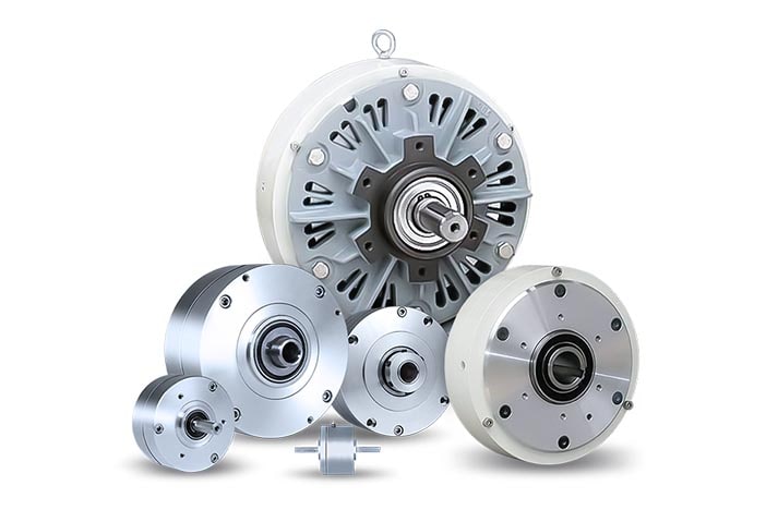
Magnetic particle brake
A magnetic particle brake is a type of electromagnetic brake that uses a magnetic field to control the torque or rotational speed of a rotating shaft or load. It is also sometimes referred to as a powder brake, particle clutch, or magnetic slip clutch.
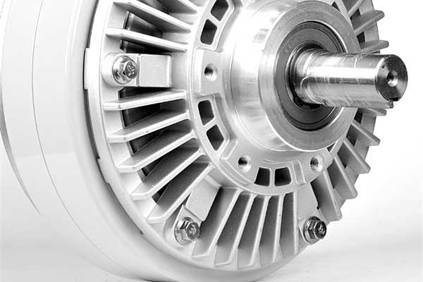
The basic structure of a magnetic particle brake consists of two main components: a rotor and a stator. The rotor is attached to the shaft or load that needs to be controlled, while the stator contains a coil that generates a magnetic field. Between the rotor and stator is a gap filled with magnetic particles, usually iron or steel.
When a current is applied to the coil in the stator, a magnetic field is created, causing the magnetic particles to align and stick together. This creates a torque transfer between the rotor and stator, allowing the brake to transmit torque or control the speed of the shaft or load.
The amount of torque or speed control is proportional to the strength of the magnetic field, which can be adjusted by varying the current supplied to the coil. This allows for precise and accurate control of the torque or speed of the shaft or load.
Magnetic particle brakes are commonly used in a wide range of industrial applications, such as in printing presses, wire and cable machinery, and packaging equipment. They are preferred in applications where a smooth, constant torque is required, and where precision and accuracy are critical.
Magnetic particle clutch
A magnetic particle clutch is a type of electromagnetic clutch that uses a magnetic field to control the torque transfer between two rotating shafts. It is similar to a magnetic particle brake but is designed for different applications.
The magnetic particle clutch consists of two rotating shafts: the input shaft and the output shaft. Between these two shafts is a gap filled with magnetic particles, usually iron or steel. The input shaft is attached to a coil that generates a magnetic field, while the output shaft is connected to a load that needs to be controlled.
When a current is applied to the coil, a magnetic field is created, causing the magnetic particles in the gap to align and stick together. This creates a torque transfer between the input and output shafts, allowing the clutch to transmit torque.
The amount of torque transfer is proportional to the strength of the magnetic field, which can be adjusted by varying the current supplied to the coil. This allows for precise and accurate control of the torque transfer between the input and output shafts.
Magnetic particle clutches are commonly used in industrial applications, such as in printing presses, wire and cable machinery, and textile machines. They are preferred in applications where a smooth and precise torque transfer is required, and where speed control is not a critical factor.
Top 5 differences between the magnetic particle clutches and brakes
Although magnetic particle clutches and brakes have similar designs and work on the same principle of magnetic particle attraction and alignment to transfer torque, there are some key differences between them:
- Function: The primary difference between the magnetic particle clutch and brake is their function. The clutch is designed to transfer torque from the input shaft to the output shaft, while the brake is designed to slow down or stop the output shaft.
- Torque transfer direction: In a magnetic particle clutch, torque is transferred from the input shaft to the output shaft, while in a magnetic particle brake, torque is transferred from the output shaft to the input shaft.
- Applications: Magnetic particle clutches are commonly used in industrial applications where precise control of torque transfer is required, such as in printing presses, wire and cable machinery, and textile machines. Magnetic particle brakes, on the other hand, are commonly used in applications where it is necessary to slow down or stop rotating machinery, such as in conveyors, packaging machines, and paper mills.
- Operating conditions: Magnetic particle clutches and brakes can operate in different environmental conditions. For instance, brakes are often used in high-temperature applications where they are exposed to extreme heat. Clutches, on the other hand, are more commonly used in low-temperature applications, where they are less likely to experience high temperatures that can affect their performance.
- Design: While magnetic particle clutches and brakes have similar designs, the construction of the two devices differs slightly. For instance, the brake may have an additional component, such as a disc or pad, that helps to dissipate heat generated during operation. The clutch, on the other hand, may have a different kind of input shaft that is designed to handle the transfer of torque more efficiently.