Magnetic Powder Brakes for Tension Control/Magnetic Powder Clutch Manufacturer
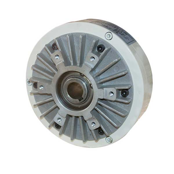
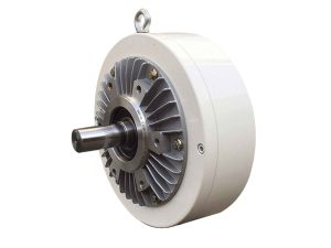
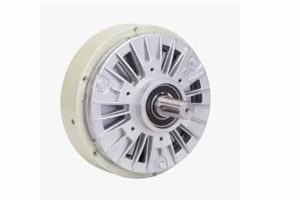
Magnetic Particle Brakes
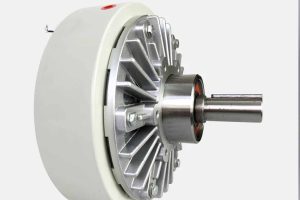
Magnetic Particle Clutches
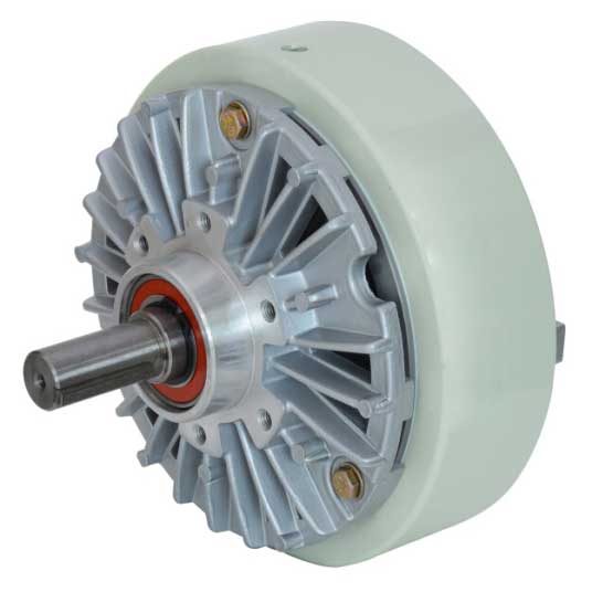
Table of Contents
What are Magnetic Particle Brakes
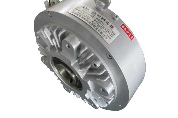
Magnetic particle brakes(Magnetic Powder Brakes) are a type of braking system that uses the principle of electromagnetism to provide a controlled and adjustable braking force. These brakes consist of a rotor, a stator, and magnetic particles that are located between them. Magnetic Particle Brakes(Magnetic Powder Brakes) are based on the electromagnetic principle and use magnetic powder to transmit torque. It has the characteristic that the excitation current and the transmission torque are basically in a linear relationship.
When a voltage is applied to the stator, a magnetic field is generated which attracts the magnetic particles toward it. As a result, the rotor starts to slow down or come to a stop, depending on the strength of the magnetic field applied. Magnetic Particle Brakes(Magnetic Powder Brakes) can transmit a certain torque irrespective of slip and has the advantages of fast response speed, simple structure, no pollution, no noise, no shock vibration, and energy saving.
One of the significant advantages of magnetic particle brakes(Magnetic Powder Brakes) is that they provide precise and accurate control over the amount of braking force generated. They are widely used in a variety of industries, including printing, packaging, textiles, and automation, among others, where controlled stopping or tension control is critical.
Magnetic Particle Brakes(Magnetic Powder Brakes) are also often used for dynamometric loading and braking of transmission machinery.
Read More: Magnetic particle clutch Wikipedia
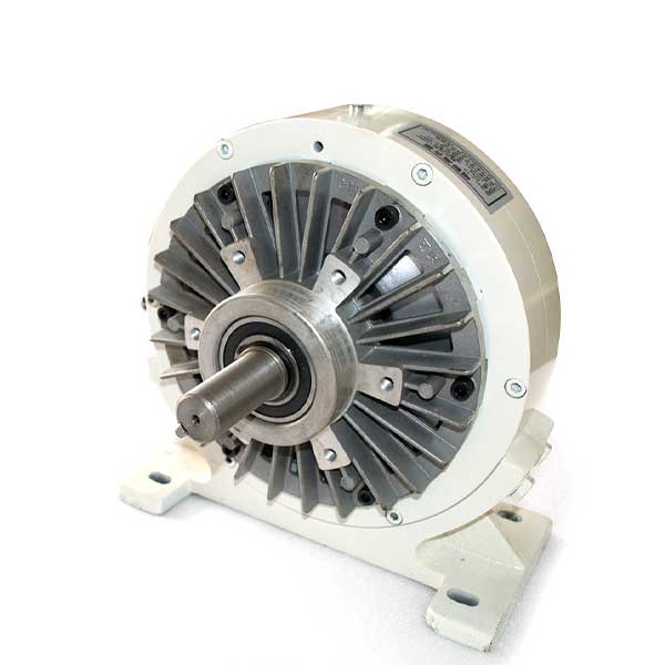
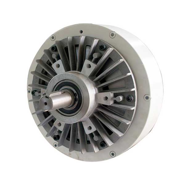
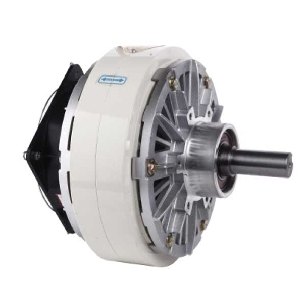
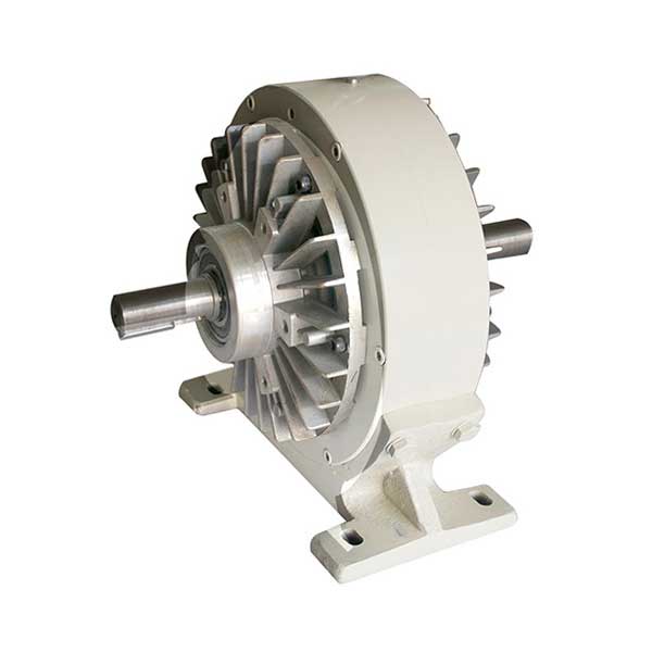
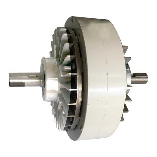
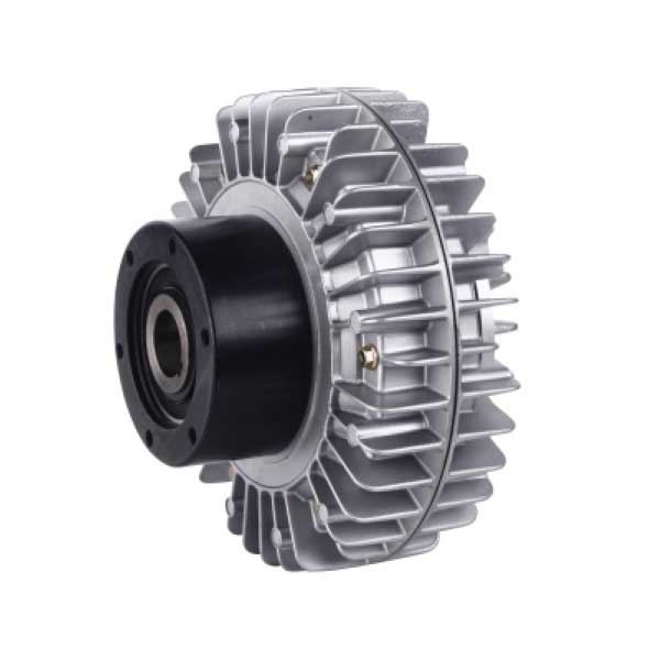
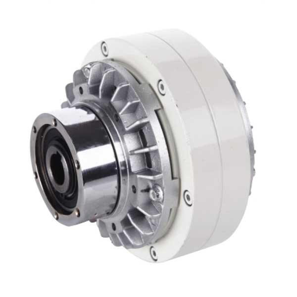
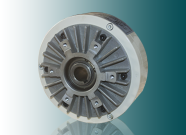
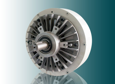
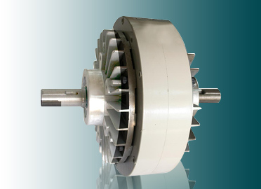
4 Models of Magnetic Particle Brakes
4 Models of Magnetic Particle Clutches
Working Principle
The Magnetic Particle Brakes(Magnetic Powder Brakes) are composed of a transmission unit (input shaft) and a driven unit (output shaft). The space between the two sets of cells is filled with granulated magnetic powder (approximately 40 microns in volume). When the magnetic coil is non-conductive, the torque will not be transmitted from the drive shaft to the driven shaft, but if the coil is electromagnetically energized, the magnetic powder will be attracted to harden due to the action of the magnetic force, and the torque will be transmitted between successive slips. . *Magnetic powder brake is an automatic control element with superior performance. It uses magnetic powder as the working medium and excitation current as the control method to achieve the purpose of controlling braking or transmitting torque. The output torque has a good linear relationship with the excitation powder current and has nothing to do with the speed or slip, and has the advantages of fast response speed and simple structure.
Three Principles
- Magnetic Particle Brakes(Magnetic Powder Brakes) are a new type of transmission element that uses magnetic powder as the medium and forms a magnetic powder chain to transmit torque under the condition of electrification. It is mainly composed of an inner rotor, outer rotor, excitation coil, and magnetic powder.
- When the coil is not energized, the active rotor rotates. Due to the centrifugal force, the magnetic powder is thrown on the inner wall of the active rotor. There is no contact between the magnetic powder and the driven rotor, and the active rotor runs idly.
- After the DC power supply is turned on, an electromagnetic field is generated, and the magnetic powder of the working medium forms a magnetic powder chain under the action of the magnetic force line, which connects the inner rotor and the outer rotor, so as to achieve the purpose of transmitting and braking torque.
Application
Magnetic Particle Brakes(Magnetic Powder Brakes) have been widely used in papermaking, printing, plastics, rubber, textile, printing and dyeing, wire and cable, metallurgy, and other related coiling and processing industries in the control of unwinding and winding tension. In addition, the Magnetic Particle Clutches(Magnetic Powder Clutches) can also be used for buffer starting, overload protection, speed regulation, etc. Magnetic Particle Brakes(Magnetic Powder Brakes) are also often used for dynamometric loading and braking of transmission machinery.
- Buffer start and stop: The smooth characteristic and constant torque characteristic of the connection are used to achieve buffer start and stop.
- Continuous sliding, tension control
- Torque Limiter
- high-speed response
- power absorption
- Positioning stop
- simulated load
Features
- High-precision torque control The torque control range is very wide, and the control precision is high. The transmission torque and the excitation current are in the correct ratio, which can realize high-precision control.
- Superior durability and long life Using super alloy magnetic powder with strong heat resistance, wear resistance, oxidation resistance, and corrosion resistance, it has a long life.
- Excellent stability of constant torque characteristics The magnetic properties of the magnetic powder are good, the bonding force between the powder particles is stable, the sliding torque is very stable, and the relative rotation speed can maintain a constant torque for a long time.
- Continuous sliding operation The cooling structure with excellent heat dissipation effect and uniform thermal deformation, coupled with the high heat resistance of magnetic powder, allows large connection and braking power and sliding power and can slide smoothly without causing vibration.
- Smooth connection, no shock The shock during connection is very small, and it can start and stop smoothly without shock. And the resistance torque is extremely small, and it will not cause useless heat generation.
- Suitable for high-frequency operation Quick response and special heat dissipation structure, suitable for high-frequency operation.
- Lightweight, maintenance-free, long service life Simple and lightweight type, using high-temperature resistant coils and special grease bearings and applying special wear-resistant treatment to the armature that is prone to wear to prolong the service life.
Top 10 Benefits of Magnetic Particle Clutches
Benefit 1: Precise Control
- Spherical particles provide smooth torque independent of speed. Low-speed chatter is also eliminated.
- The magnetic circuit is designed to produce torque proportional to current.
- Unique design requires only one powder seal, thus reducing drag torque and allowing for a wider operating range.
Benefit 2: Extremely Long Life
- Spherical particles made from alloy provide outstanding resistance to corrosion and mechanical breakdown.
Benefit 3: High Heat Dissipation.
- One of the models, the PTB, uses a heat pipe that provides heat dissipation levels equal to water-cooled units and several times greater than natural cooling.
- The shaft-mounted clutches provide self-cooling through the use of an integral fan that rotates with the input.
Benefit 4: Clean Operation
- All models are completely enclosed. Ideal for applications where clean operation is desired.
Benefit 5: Easy to Mount
- Precision pilots are provided to position units for easy installation.
- Clutches and brakes with hollow bores are offered for applications where shaft mounting is desired.
Benefit 6: Smooth Engagement
- Torque characteristics provide for smooth and controllable acceleration or deceleration of the load.
Benefit 7: Fast Response
- Fine particles respond quickly to the field for millisecond engagement if required.
Benefit 8: No Maintenance
- Adjustment or lubrication is not required.
Benefit 9: Quiet Operation
- Engagement is smooth and quiet.
Benefit 10: Low Current Draw
- An efficient magnetic circuit design allows for a minimal current draw.
Install
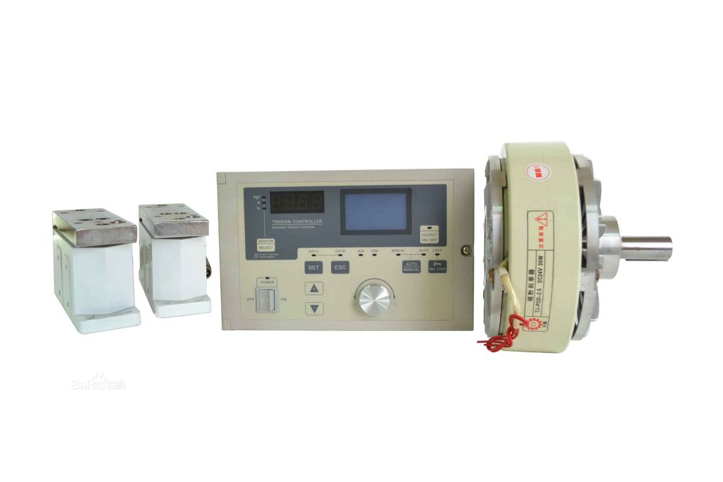
- The Magnetic Particle Brakes(Magnetic Powder Brakes) use a direct current as the excitation power source.
- The Magnetic Particle Brakes drive shaft is installed horizontally; the installation accuracy of the drive shaft and the coupling is H8/f8; it is forbidden to use a hammer to strike the assembly; the installation coaxially of the drive shaft and the shaft connected to it is +0.03mm.
- During the transportation of the Magnetic Particle Brakes(Magnetic Powder Brakes) , the magnetic powder often gathers somewhere, which may cause a “stuck” phenomenon. You can flip the brake as a whole to loosen the magnetic powder, or use a lever to pry it. In order to prevent the precipitation of magnetic powder during transportation, the Magnetic Particle Brakes(Magnetic Powder Brakes) above CZ-50 should pour out the magnetic powder after the test and install it separately, and the magnetic powder can be gradually injected from the magnetic powder hole during the running-in process.
- The water-cooled Magnetic Particle Brakes(Magnetic Powder Brakes) should run with water first, and it is forbidden to run without water (water pressure 1.5~3kg/cm2). The inlet and outlet pipes should be distributed up and down, with the inlet pipe at the bottom and the outlet pipe at the top.
- The Magnetic Particle Brakes do not support the installation method that radially bears the main drive force.
- Before the Magnetic Particle Brakes(Magnetic Powder Brakes) are used for the first time, 30% of the rated current is applied, and after running for 10 seconds, the power is turned off and then turned on again, and repeated several times to ensure the fluidity and uniform distribution of the magnetic powder.
- The Magnetic Particle Brakes cannot be used with excessive torque and rotation speed, otherwise, the magnetic powder life will drop sharply, or there will be powder leakage and stuck.
Precautions
- Be careful to avoid installation deviations during the installation
- Tightening the gland should be carried out after the coupling is aligned, and the bolts should be evenly supported to prevent the end face of the gland from being skewed. Check each point with a feeler gauge, and the error should not be greater than 0.05 mm.
- Check the matching clearance (ie concentricity) between the gland and the shaft or the outer diameter of the shaft sleeve. It should be uniform around it. Use a feeler gauge to check that the tolerance at each point is not greater than 0.01 mm.
- The amount of spring compression should be carried out in accordance with the regulations, and it is not allowed to be too large or too small, and the error is required to be 2.00 mm. If it is too large, the specific pressure of the end face will increase, and the end face will be worn at another speed. If it is too small, the specific pressure will be insufficient and the sealing effect cannot be achieved.
- After the moving ring is installed, the beard is guaranteed to be able to move flexibly on the shaft, and it should automatically spring back after pressing the moving ring against the spring.
Precautions when disassembling
- Be careful when disassembling the mechanical seal, and it is strictly forbidden to use a hand hammer and a flat shovel to avoid damage to the sealing element. A pair of wire hooks can be made, and the sealing device can be pulled out by extending into the gap of the transmission seat in the direction of self-financing. If the scale cannot be removed, it should be cleaned and then removed.
- If mechanical seals are used at both ends of the pump, take care of each other during assembly and disassembly to prevent one from losing the other.
- For the mechanical seal that has been run, if the gland is loose and the seal moves, the dynamic and static ring parts must be replaced, and should not be re-tightened for continued use. Because the original running track of the friction pair will change after the same movement, the sealing performance of the contact surface is easily damaged.
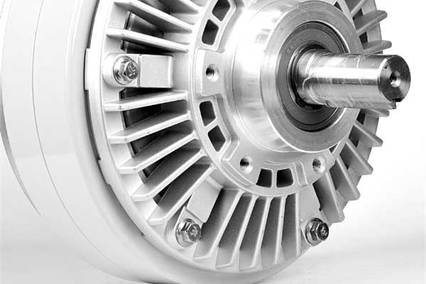
Heat dissipation conditions
The heat dissipation of the Magnetic Particle Brakes generally only relies on two aluminum back covers (self-cooling or air-cooling), or other heat dissipation devices.
The most common types of Magnetic Particle Brakes heat dissipation are self-cooling and water-cooling. The self-cooling type uses the aluminum shell cover of the Magnetic Particle Brakes(Magnetic Powder Brakes) itself to dissipate heat and the surrounding airflow environment, while the water-cooled type relies on water to make the Magnetic Particle Brakes internal and external. The surface temperature is lowered, thereby improving the use and performance of the magnetic powder.
The main purpose of these two heat dissipation methods is to reduce the temperature inside and on the surface of the Magnetic Particle Brakes(Magnetic Powder Brakes) and to improve the service life, performance, and work efficiency of the Magnetic Particle Brakes and the magnetic powder.
How to Determining Proper Brake Size
- Have sufficient torque
- Be able to dissipate the heat
- No run above rated speed
Torque
- For load simulation, torque limiting, and similar applications, torque is already known.
- For web handling, torque must be calculated. First determine the desired tension in your web (wire, fabric, film, etc.).
Calculate Torque: Torque (lb-inches) = Tension (lbs) x Roll Diameter (inches) x 0.5
Use the Full Roll Diameter for calculating the maximum torque needed. For applications with the web running over a pulley or between nip rollers (pinch rollers), use the pulley diameter as the roll diameter in the formula above. Always be conservative – select the next larger model if the application requires nearly the rated torque
RPM (must be less than the maximum allowable)
- For load simulation, torque limiting, and similar applications, RPM is already known.
- For web handling, usually linear speed (Web Speed) is known, and RPM must be calculated.
Calculate RPM: RPM = 3.8 x WEB SPEED (feet per minute) / ROLL DIAMETER (inches)
Use the Full Roll Diameter to determine the slowest speed. Use the Core Diameter (empty spool diameter), to determine the fastest speed. For applications with the web running over a pulley or between nip rollers (pinch rollers), use the pulley diameter as the roll diameter.
Slip Heat Dissipation
(model must be physically large enough not to overheat)
- For any application.
Calculate Heat Input: HEAT (watts) = TORQUE (lb-inches) x RPM x 0.012 - For unwinding applications.
Calculate Heat Input: HEAT (watts) = WEB TENSION (lbs) x WEB SPEED (feet/minute) / 44
Duty Cycle
The average heat input must be below the brake’s heat dissipation rating. If the motion is intermittent, use the average speed for thermal (SLIP) calculations.
Seven questions and answers about magnetic particle brakes
What’s the difference between a brake and a clutch?
Brakes – When the coil is energized, the brake shaft is coupled to the housing. Typical uses are to provide adjustable tension for unwinding webs (paper, wire, film, etc.), and also to provide an adjustable torque load to a motor under test (typically stepper or gear motors).
Clutches – When the coil is energized, the clutch input shaft is coupled to the clutch output shaft. Typical uses are to provide adjustable tension for rewinding webs, and precision torque limiting (tightening fasteners & bottle caps).
Both brakes and clutches have the same torque and tension characteristics.
Can brakes & clutches be operated at maximum RPM and rated torque simultaneously?
No, because of heat dissipation limits.
Brakes and clutches run at rated torque and maximum RPM would overheat quickly.
Maximum allowable slip torque and slip RPM can be determined by using the formula for heat dissipation.
Is torque available at low or zero RPM?
Yes. Full torque is available even at zero RPM.
However, slip torque is not perfectly smooth below about 20 RPM (depending on driveline stiffness) due to ‘slip-stick’, also called ‘chatter’. The amount may not be noticeable under many conditions.
If the web is not elastic, slow RPM is probably OK.
Unwinding a very elastic web at a very low RPM is not recommended. The web will stretch, then the brake will release, then the web will contract.
How is torque calculated, to tension a roll of material?
First, decide desired web tension & maximum roll diameter. Then, use the formula for determining torque.
What is the accuracy of the torque?
When manufactured, rated torque is adjusted from -0 percent to +25 percent. (Precision torque available: Brakes: -0 to +10 percent. Clutches: -0 to +15%). The torque is precise.
Torque will repeat short term within +/-2 percent from cycle to cycle. But with extended usage, torque can vary +/-5 percent from initial factory settings. After months of continuous usage, torque will decrease due to wear and fretting corrosion of the stainless steel magnetic particles. A higher input current can compensate for the decreased torque for quite a while.
For applications requiring better accuracy, uses a torque transducer as a feedback device, (or a tension transducer on a web), to measure actual torque (or tension). Then vary the voltage to the brake or clutch for high accuracy.
Is the torque vs. current graph a single line?
No. Magnetic particle brakes(Magnetic Powder Brakes) & clutches exhibit hysteresis. If the input current is increased from zero to the rated current, and then the input current is decreased from the rated current to zero, 2 different lines are graphed. The 2nd line indicates higher torque.
If the current is increased from zero to about 1/2 of the rated current and then decreased, the decreasing graphed line will be between the upper and lower lines.
When high accuracy is needed, always start at 0 amps, or always start at the rated current. If this is not practical, either use a torque transducer as a feedback device to measure torque, or determine experimentally the current needed at your various settings, and repeat this pattern during usage.
Should magnetic particle brakes and clutches be used as safety devices?
No. Avoid applications where failure could cause personal injury or loss of property.
Event and Update
Hollow Shaft Magnetic Particle Clutch vs. Solid Shaft Magnetic Particle Clutch: Key Differences Between the Two Types
Magnetic particle clutches are versatile devices used in various industrial applications for transmitting torque and controlling rotational motion.
Precautions For The Use Of Magnetic Particle Brakes
Magnetic Particle brake can easily control the torque within the range of 5% to 100% of rated torque by changing the magnitude of excitation current, and the e…
Magnetic Particle Clutch:Working principle And Application
Magnetic Particle clutch, also known as electromagnetic Particle clutch, is based on electromagnetic principle and uses magnetic Particle to transmit torque.